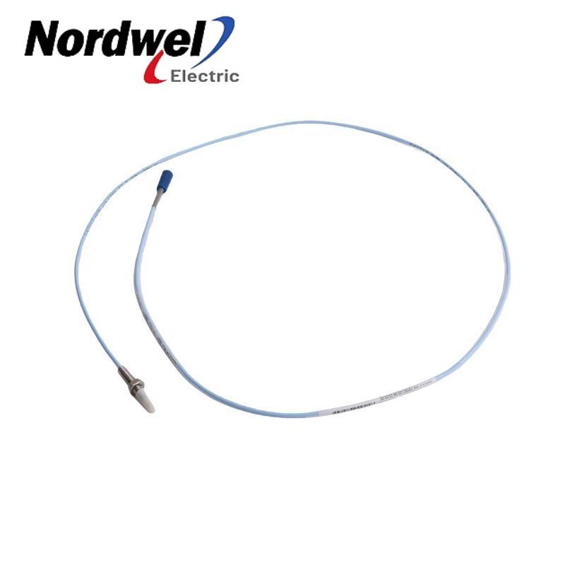
A practical guide to deciding when a Bently Nevada 990 transmitter is an efficient brownfield solution—and when the maintenance question demands more than one analog trend.
Brownfield modernization is often discussed as a race toward more connected equipment. For a small pump, motor, fan or centrifugal air compressor, however, the first requirement may be much simpler: deliver a continuous, proportional shaft-vibration value to the machinery control system without rebuilding the complete protection architecture.
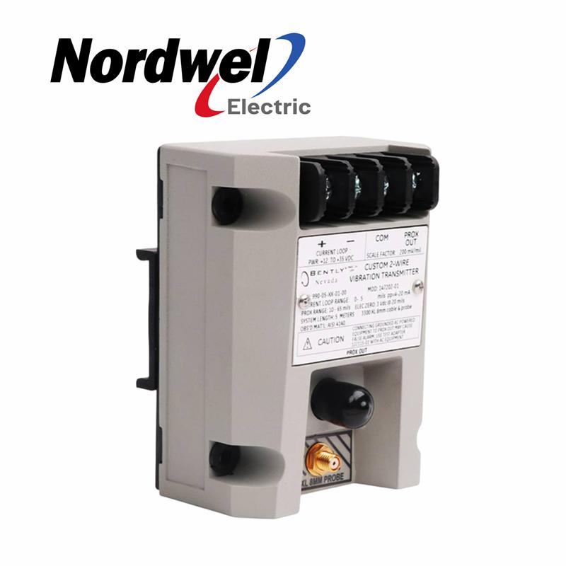
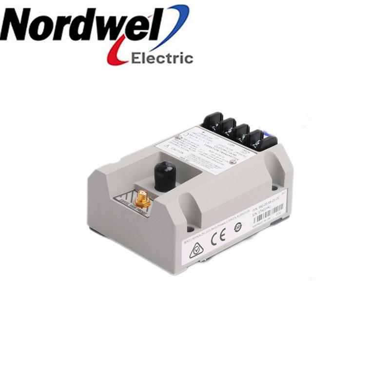
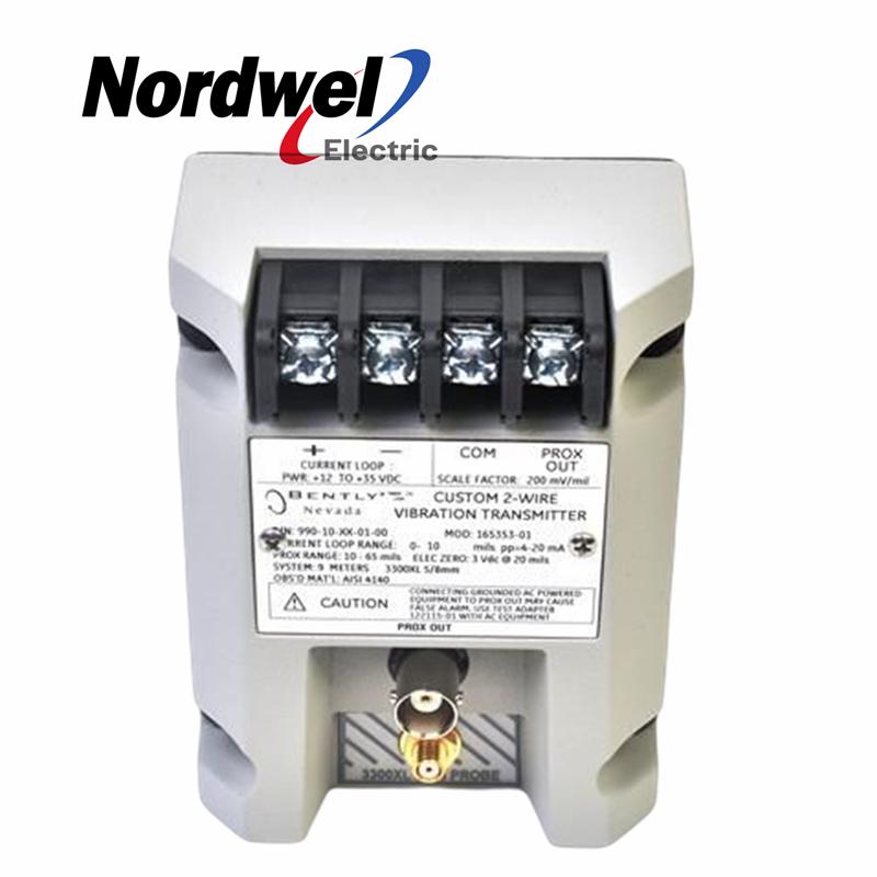
That is the problem the Bently Nevada 990 addresses. It accepts one non-contacting 3300 NSv proximity probe and matching extension cable, conditions the signal into peak-to-peak vibration amplitude, and sends a proportional 4–20 mA value to a PLC, DCS or other machinery control system where alarming and logic occur. The decision is not whether analog technology is fashionable. The decision is whether this signal contains enough information for the operating action you expect it to support.
This distinction is especially important in a brownfield project. Reusing an available analog input can reduce cabinet work and shorten commissioning, but it does not remove the need to confirm the measurement purpose. A shaft-relative vibration value is useful only when the bearing arrangement, target surface and alarm philosophy are suitable for that measurement. The lowest-cost transmitter is not the lowest-risk choice if the machine team expects information the loop cannot deliver.
Before requesting a quotation, document the machine, bearing type, expected vibration range, installed probe details, available supply voltage and the action attached to each alarm level. These inputs allow procurement and engineering to discuss one defined measurement chain instead of comparing transmitter names in isolation. They also make it easier to identify whether the project is a straightforward loop retrofit or an architecture decision that requires wider diagnostic capability.
The plant already has analog inputs and alarm logic, so a complete rack may feel disproportionate to the machine risk.
Small shafts, narrow side views and compact cabinets make standard sensing arrangements difficult to install.
A loose connector or failed probe must not be mistaken for a genuine high-vibration event.
A trend may show that vibration increased, but maintenance may still need phase and waveform information to explain why.
Every stage can preserve—or weaken—the meaning of the final 4–20 mA value.
The 990 should therefore be treated as one element of a calibrated system rather than as a standalone current source. The probe, extension cable and transmitter must correspond to the selected 5 m or 7 m electrical system length. Mechanical fit alone is not proof of compatibility, and a mixed chain can produce a believable current value while weakening the relationship between actual shaft motion and the displayed engineering units.
The receiving channel also belongs to the measurement chain. Its input resistance, scaling, alarm delays and instrument-fault logic determine how the current is interpreted. A correct transmitter connected to an incorrectly ranged PLC card can create false confidence: the trend may look smooth, but the displayed amplitude and alarm thresholds will not represent the ordered full-scale range.
Confirm that shaft-relative vibration is the intended measurement.
Thread, case, total length, connector and approval suffix matter.
Probe plus cable must produce the selected 5 m or 7 m system length.
Converts peak-to-peak amplitude into the selected 4–20 mA span.
Scaling, alarm, delay, voting and trip philosophy live in the control system.
The manufacturer describes 4–20 mA vibration transmitters as suitable for overall vibration trending, while noting limited diagnostic capability. The control system sees peak-to-peak trend data; it does not gain vibration phase from the current loop.
Functions such as gap alarms, phase alarms, Timed OK channel defeat, Danger Bypass and Trip Multiply are not provided through this arrangement. PLC data from the transmitter is not a substitute for a plantwide diagnostic platform such as System 1. This boundary should be written into the retrofit scope before the hardware is ordered.
| Parameter | Official value | Why the retrofit team cares |
|---|---|---|
| Transmitter input | One 3300 NSv probe plus extension cable | Do not select by connector appearance or “proximity probe” family name alone. |
| Terminal power | +12 to +35 Vdc | Verify voltage at the transmitter under full loop load, not only at the supply. |
| Current output | 4–20 mAdc, two-wire | Scale the PLC/DCS channel to the ordered full-scale vibration range. |
| Loop accuracy | Within ±1.5% over the selected full-scale range, with stated test conditions | The figure is additional to Prox Out incremental scale-factor effects. |
| Probe gap | 0.5 to 1.75 mm (20 to 55 mils) | The probe must remain in this region to support the full-scale measurement. |
| Maximum loop resistance | 1,000 Ω including cable at 35 Vdc | Excess resistance can prevent the output from reaching 20 mA. |
| Not OK behavior | Output goes below 3.6 mA within 100 µs; recovery takes about 2–3 seconds | Program the control system to distinguish instrument health from low vibration. |
| Ordered full-scale options | 0–4, 0–5, 0–8 or 0–10 mils pp (0–100, 125, 200 or 250 µm pp) | An incorrect span weakens resolution or causes avoidable saturation. |
Specifications depend on stated manufacturer test conditions and the exact configured product. Always verify the current revision, approvals and order code for the application.
Loop power should be checked as a voltage budget, not as a nameplate value. Cable resistance, the analog input, intrinsic-safety barriers and isolators all consume available voltage. The manufacturer states a maximum loop resistance of 1,000 Ω at 35 Vdc; the allowable resistance is lower when the supply voltage is lower. Commissioning should verify the voltage at the transmitter while the loop is operating, including the condition near full-scale current.
Instrument health requires its own PLC/DCS state. A probe fault or loose connection drives the output below 3.6 mA, and the transmitter also holds the output below this level briefly during power-up. This current must not be interpreted as exceptionally low vibration. Separate tags, alarms or quality logic for “measurement unavailable” help the operator distinguish a healthy quiet machine from a failed measurement chain.
A proximity system measures shaft motion relative to the probe mounting location. It should not be selected as if it were a casing-mounted accelerometer or velocity transmitter.
The probe cable plus extension cable must match the ordered transmitter system length. A connector that fits does not prove electrical compatibility.
Published specifications use defined target material and geometry. Shaft material, target size, surface condition and electrical runout can affect the result.
A loop can produce a signal while operating too close to one end of its linear region. Verify gap voltage and mechanical clearance through the full shaft movement.
Cable, input resistance, barriers and isolators all consume voltage margin. At excessive resistance, the signal may trend normally at low vibration but fail to reach 20 mA.
The Not OK circuit drives the output below 3.6 mA for a failed probe, loose connection or startup inhibit. PLC/DCS logic must classify instrument health separately from low vibration.
Because the output is non-isolated, this connection can cause a false alarm. Use the specified test adapter or appropriately isolated equipment.
Machine type, bearing type, shaft diameter, measurement direction, target material, expected vibration and required action are documented.
Full-scale, 5 m or 7 m length, mounting and approval suffix are matched to the probe and extension cable.
Supply voltage, resistance, cable, shield, barriers, receiver scaling, Not OK handling and alarm logic are reviewed.
Probe gap, loop zero/span, simulated output, Not OK response, displayed engineering units and final records are verified.
The standard ordering structure is 990-AA-BB-CC-DD. Every group changes something the engineering team must understand. A quotation that says only “Bently Nevada 990” is therefore incomplete: two devices from the same family can represent different ranges, electrical system lengths, mounting arrangements and approvals.
Full-scale range is an engineering choice, not merely a purchasing preference. A range that is unnecessarily wide reduces the share of the current span used during normal operation, while a range that is too narrow can reach the top of the loop before the intended alarm or trip level. The ordered range, receiver scaling and alarm setpoints should be reviewed together so that 4 mA, 20 mA and every value between them have one agreed meaning.
The same discipline applies to system length, mounting and approvals. Substituting a suffix to obtain faster delivery can change compatibility with the installed probe chain, cabinet arrangement or project documentation. If an exact code is unavailable, record the proposed deviation and obtain an engineering review before accepting the alternative. This prevents a commercially convenient substitution from becoming a field rework problem.
Selects 4, 5, 8 or 10 mils peak-to-peak, corresponding to 100, 125, 200 or 250 µm pp. The PLC/DCS engineering range must match.
Selects the 5.0 m or 7.0 m proximity system. This is a property of the complete probe-and-extension-cable chain, not the cabinet distance.
Selects 35 mm DIN clips, bulkhead screws, or both. Check cabinet rail, access, bend radius and space for diagnostic connections.
Selects no agency approval or defined approval packages. Confirm the current approval documentation for the destination and area classification.
State what the operator must do when vibration changes: investigate, alarm, reduce load or trip. This determines the required measurement quality and architecture.
Confirm bearing type, shaft or target material, available view, probe thread, clearance, bracket stiffness and the expected relative motion through all operating states.
Select probe, connector, armor, total probe length, extension-cable length and 990 system-length option as one measurement system.
Calculate resistance and voltage margin, review barriers and isolators, specify shield termination, and verify that the selected receiver can interpret Not OK current correctly.
Use the test input and approved procedure to check zero, span, engineering units, alarm thresholds, Not OK behavior and the operator display before site installation.
Record gap voltage, loop current, displayed value, alarms, wiring, final suffixes and photographs. A future replacement is safer when the original acceptance evidence is retrievable.
For a useful compatibility review, provide the complete 990 order code, probe code, extension-cable code, machine type, shaft or target details, PLC/DCS input information, required quantity and clear label photographs.
Phone / WhatsApp: +86 18030235313These are exact Nordwel product pages. Verify the full configured suffix for the application.
No. It remains useful when the requirement is a proportional overall vibration value for an existing control system. It becomes insufficient when the decision depends on permanently available phase, waveform or advanced diagnostic functions.
The 990 provides a standard two-wire 4–20 mA signal intended for a machinery control system. The actual loop must still be checked for supply voltage, total resistance, barriers or isolators, scaling, grounding and alarm logic.
No. It accepts a non-contacting 3300 NSv proximity system and reports shaft-relative peak-to-peak vibration. A casing-mounted seismic transmitter addresses a different measurement.
Do not make that assumption. Confirm the complete probe and extension-cable codes, the total 5 m or 7 m electrical system length, connector, approvals, mounting and the selected 990 option.
It indicates a Not OK condition, including a faulty probe or loose connection. The output is also held below 3.6 mA briefly during power-up. Control logic should identify this as instrument status, not a very low vibration reading.
Only when the test equipment is battery-powered or appropriately isolated. For grounded AC-powered equipment, the manufacturer strongly recommends the 122115-01 test adapter to isolate and condition the signal.
The available voltage may be insufficient for the total loop resistance. When resistance is too high, the transmitter may not reach 20 mA even though low-current operation appears normal.
The official datasheet states that PLCs connected to the transmitter provide peak-to-peak trend data and are not suitable as a plantwide diagnostic source for System 1 or Rule Paks. Use an architecture designed for the diagnostic requirement.
The ordering structure offers 4, 5, 8 and 10 mils peak-to-peak ranges. Selection should consider expected normal vibration, alarm range, resolution and the control-system engineering scale.
No. Approval is an order-code choice and must be checked against the exact product, country, area classification, barrier arrangement and current approval documentation.
Photograph the complete transmitter label, probe code, extension-cable label and connectors, plus the mounting and terminal arrangement. Also provide machine type, quantity, destination and the symptom that triggered replacement.
Use this Nordwel-hosted PDF as a technical reference. Because revisions and approval details can change, confirm the current manufacturer revision and exact configured order code before purchase or engineering approval.
Open Site PDF


Disclaimer:
Nordwel sells new and surplus products and develops channels for purchasing such products. This website has not been approved or recognized by any of the listed manufacturers or trademarks.