other
Products
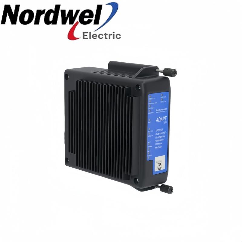
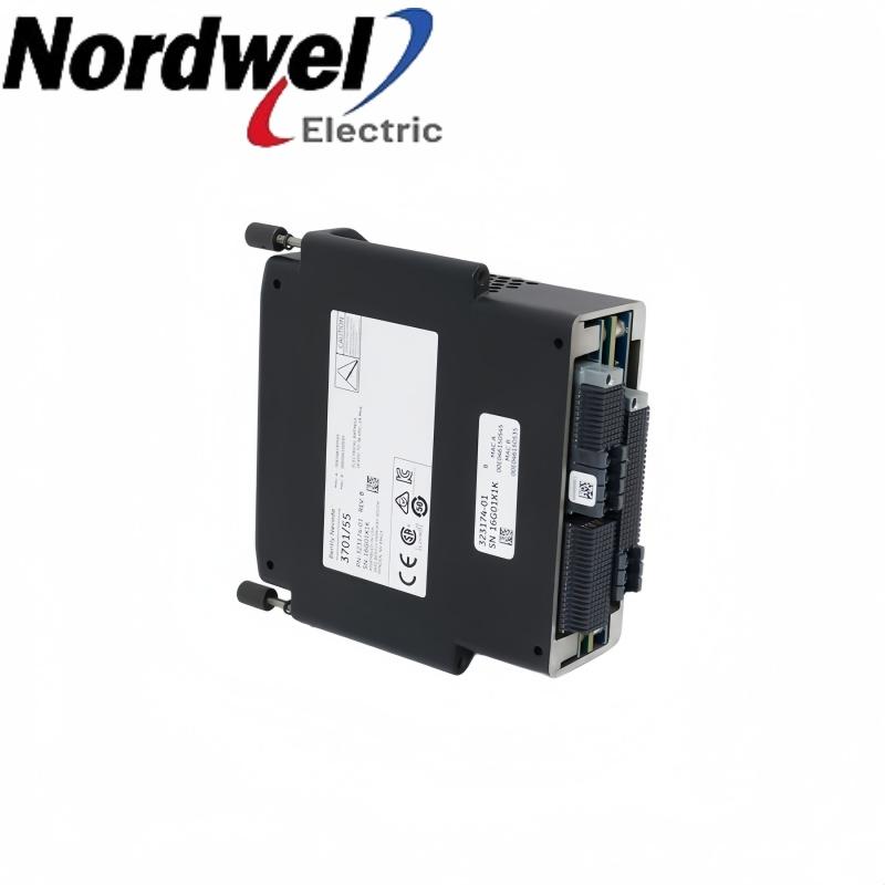
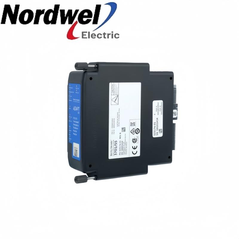
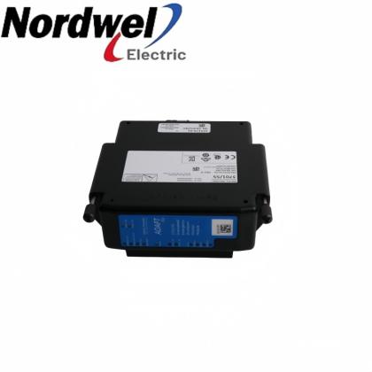
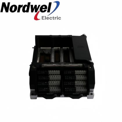
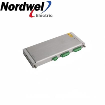
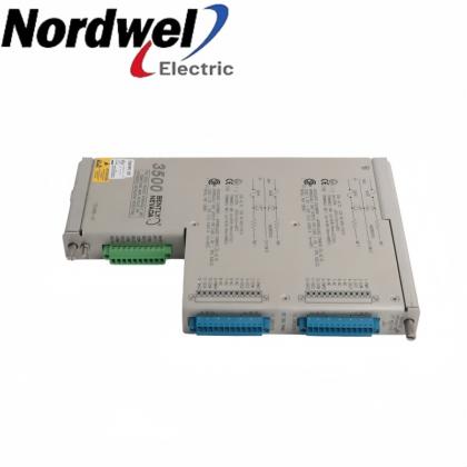
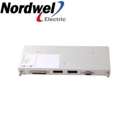
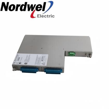
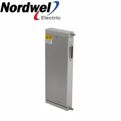
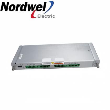
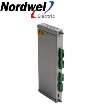
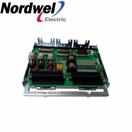
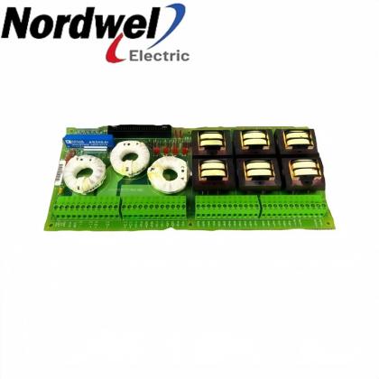
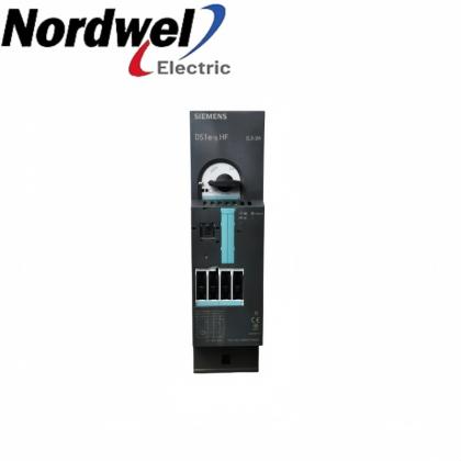
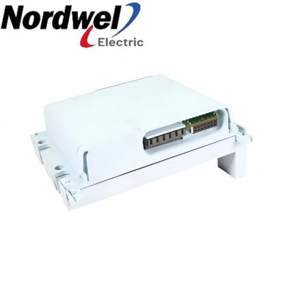
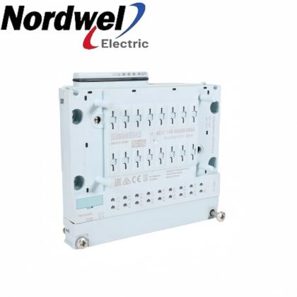
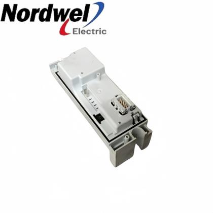
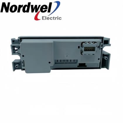
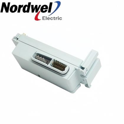
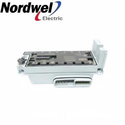
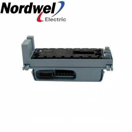
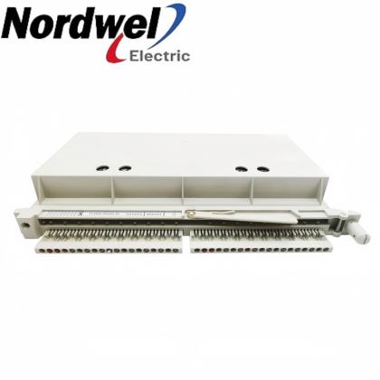
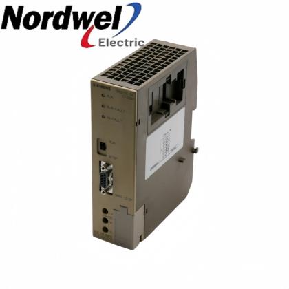
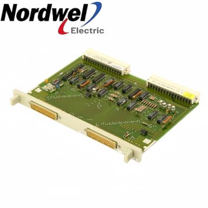
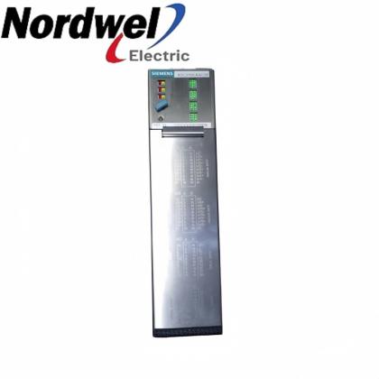
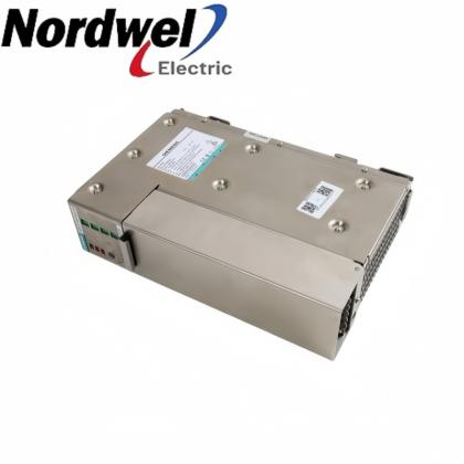
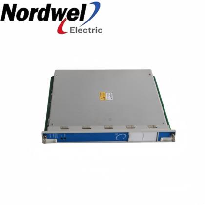
Bently Nevada 3701/55 289761-01 terminal base assembly product view

Bently Nevada 3701/55 289761-01 terminal base assembly

EMAIL SALES
Bently Nevada ADAPT ESD
3701/55 289761-01 - terminal base assembly

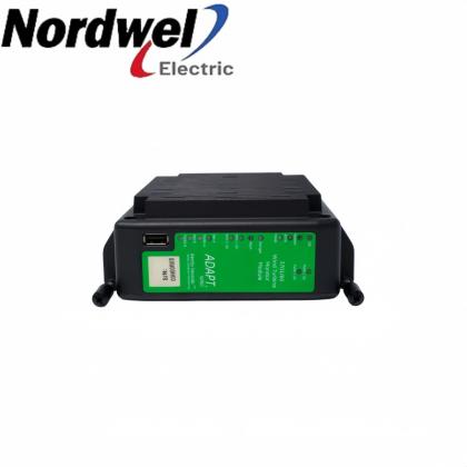
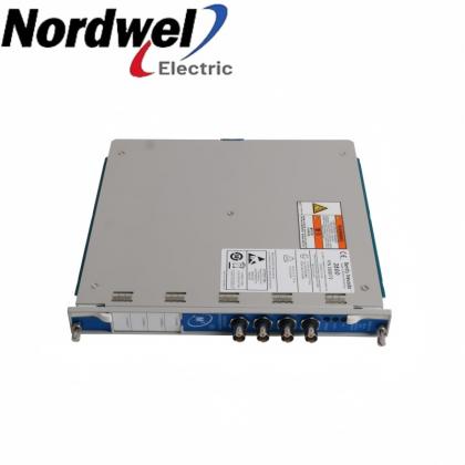
3701/55 289761-01 is the ADAPT ESD terminal base assembly. Preserve the shutdown system wiring, grounding and vertical installation layout.

Bently NevadaADAPT ESDESD terminal base
Sales managerTiffany Guan
Mobile / WhatsApp+86 18030235313
3701/55 289761-01 product profile
Product familyADAPT ESD
Exact model3701/55 289761-01
Installed CPU arrangement3 separate processor modules
Installed relay arrangement3 separate relay modules
Mounting orientationVertical; power terminals horizontal
Minimum enclosure depth9 in (228.6 mm)
  • Brand:

    Bently Nevada
  • Item NO.:

    3701/55 289761-01
3701/55 289761-01 configuration inquiry

Get a precise quote for 3701/55 289761-01

Email Sales
Sales managerTiffany Guan
WhatsApp+86 18030235313

3701/55 289761-01 functions and interfaces

3701/55 289761-01 is the terminal base assembly for the triple-redundant ADAPT emergency-shutdown installation. The complete system uses three processor modules and three relay modules mounted on the assembly. The terminal base must be installed vertically with the power terminals exiting horizontally, while the enclosure must provide the specified depth and ventilation. Processor electronics and output relay modules are separate supply items.

Module installationProvide the mechanical and interconnection platform for the fitted ESD modules.
Terminal orientationPreserve the power-terminal exit direction required for heat dissipation.
Earth-reference arrangementRetain the approved common-to-chassis jumper or external barrier-earth configuration.
Enclosure planningAllow the required enclosure depth and protect the installation from condensation and obstructed ventilation.

Installation and selection boundaries

  • A terminal base is not a CPU or a complete commissioned shutdown system.
  • Maintain the validated module arrangement, shutdown wiring and grounding design during a base replacement.
  • Do not assign complete-system power consumption, network ports or processing speed to the bare base assembly.
Official product data

3701/55 289761-01 key specifications

Spare identity Terminal base assembly for ADAPT ESD
Installed processing arrangement Three separate CPU modules in the complete system
Installed output arrangement Three separate relay modules in the complete system
Base mounting orientation Vertical
Power-terminal orientation Exiting horizontally for heat dissipation
Minimum enclosure depth 9 in (228.6 mm)
Ground-reference provision Removable common-to-chassis jumper
Certified-installation restriction Inter-terminal-base connectors remain unused for the specified SIL and hazardous-area installations

Bently Nevada 100M8833 Rev. L, ESD architecture, installation conditions, accessories and dimensional drawing (pages 1-3 and 12-15).

Pre-order check 01

Installation environment

Check the complete 3701/55 289761-01 identity and the actual installation before connection or replacement.

  • Record the existing module positions, field terminals, earth connections and validated shutdown configuration before work.
  • Mount the base vertically with its power terminals exiting horizontally and provide at least the specified nine-inch enclosure depth.
  • Preserve the required common-to-chassis jumper arrangement and the safety-barrier grounding design.
  • Keep restricted inter-terminal-base connectors unused and complete the approved safety validation before restoring protection.
Keep the approved field drawing and installation records available during verification.
Pre-order check 02

Compatibility confirmation

Match the complete component identity with the fitted interfaces and installed configuration.

Assembly role
Terminal base assembly for the specified ADAPT ESD installation, not a processing module.
Module population
Match the complete system arrangement of three processor modules and three relay modules.
Mechanical installation
Vertical base orientation, horizontal power-terminal exit and at least nine inches of enclosure depth.
Earth reference
Match the removable jumper and the actual galvanic-isolator or zener-barrier grounding design.
Safety configuration
Preserve the validated shutdown architecture and applicable connector restrictions; base replacement does not itself establish SIL compliance.
Confirm 3701/55 289761-01 against the fitted hardware, field wiring and approved commissioning records.
Recommended model families

More Bently Nevada models

Bently Nevada selection 01Bently Nevada 330130-070-01-00Bently Nevada 330130-075-01-00Bently Nevada 330104-00-08-15-02-00

Confirm the complete order code, fitted interfaces and installed-system requirements before replacement.

Bently Nevada selection 02Bently Nevada 330102-00-12-10-01-05Bently Nevada 330103-02-04-10-02-CNBently Nevada 330103-02-08-10-02-CN

Confirm the complete order code, fitted interfaces and installed-system requirements before replacement.

Bently Nevada selection 03Bently Nevada 330905-00-25-05-02-CNBently Nevada 330903-00-07-10-01-CNBently Nevada 330903-00-07-10-01-00

Confirm the complete order code, fitted interfaces and installed-system requirements before replacement.

Bently Nevada selection 04Bently Nevada 330876-03-10-00-00Bently Nevada 330906-02-12-10-02-05Bently Nevada 330902-00-95-05-02-05

Confirm the complete order code, fitted interfaces and installed-system requirements before replacement.

Additional published brands

Additional Advantage Models

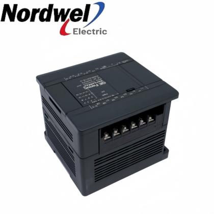
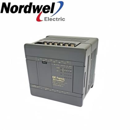
General ElectricGeneral Electric IC200UDR120General Electric IC200UDR140General Electric IC200UDR164

Confirm the complete order code, fitted interfaces and installed-system requirements before replacement.

General ElectricGeneral Electric IC200UDR228General Electric IC200UDR440General Electric IC200UEC008

Confirm the complete order code, fitted interfaces and installed-system requirements before replacement.

General ElectricGeneral Electric IC200UEC108General Electric IC200BEM104General Electric IC200CHS003

Confirm the complete order code, fitted interfaces and installed-system requirements before replacement.

General ElectricGeneral Electric IC200UAA007General Electric IC200UAL004General Electric IC200UAL005

Confirm the complete order code, fitted interfaces and installed-system requirements before replacement.

SiemensSiemens 6ES7144-4PF00-0AB0Siemens 6ES7144-4JF00-0AB0Siemens 6ES7144-4FF01-0AB0

Confirm the complete order code, fitted interfaces and installed-system requirements before replacement.

SiemensSiemens 6ES7144-1JB31-0XB0Siemens 6ES7144-1GB31-0XB0Siemens 6GK5308-2FM10-2AA3

Confirm the complete order code, fitted interfaces and installed-system requirements before replacement.

SiemensSiemens 6ES7143-5AH00-0BA0Siemens 6ES7143-4BF50-0AA0Siemens 6ES7142-6BH00-0AB0

Confirm the complete order code, fitted interfaces and installed-system requirements before replacement.

SiemensSiemens 6GK1143-0TA02Siemens 6GK1143-0AA01Siemens 6ES5945-7UA23

Confirm the complete order code, fitted interfaces and installed-system requirements before replacement.

Every model above links to an existing Nordwel product page. Send the full part number for configuration and availability confirmation. CHECK WITH SALES

3701/55 289761-01 Order Guide

Selection and replacement checks for the complete 3701/55 289761-01 ordering identity.
1Identify the assemblySpecify the complete 3701/55 289761-01 terminal-base identity.
2Capture the populationRecord all processor, relay and terminal components fitted to the base.
3Review enclosure spaceConfirm vertical installation, terminal access and required enclosure depth.
4Confirm groundingRetain the jumper and barrier-earth arrangement from the approved drawing.
5Define included hardwareList separately required modules, terminals and enclosure items in the quotation.
6Arrange validationSchedule controlled isolation, reassembly and shutdown-system validation.

Middle East Demand & Specialist Models

Selected specialist-brand products requested for regional projects and available on Nordwel.

Check the complete ordering identity, fitted interfaces and application requirements before selection.
General ElectricIC200UDR040

Match the complete model, revision and required installed function before ordering.

Specialist model
General ElectricIC200UDR064

Match the complete model, revision and required installed function before ordering.

Specialist model
General ElectricIC200UAL006

Match the complete model, revision and required installed function before ordering.

Specialist model
General ElectricIC200UAR028

Match the complete model, revision and required installed function before ordering.

Specialist model
General ElectricIC200UDD112

Match the complete model, revision and required installed function before ordering.

Specialist model
General ElectricIC200UDD120

Match the complete model, revision and required installed function before ordering.

Specialist model
Nordwel customer support

Company Services & FAQ

Practical support for 3701/55 289761-01 selection, quotation and replacement planning.

Company services

Component and installation checkReview the complete model, actual interfaces and installed configuration before quotation.
Fast quotation supportConfirm pricing, availability and lead time against current Nordwel business records.
Worldwide shipping coordinationConfirm destination, freight option, packing requirements and shipment tracking workflow.
Order follow-upProvide pre-order clarification and shipment-status support through the assigned sales contact.

3701/55 289761-01 FAQ

What does the 3701/55 289761-01 ordering identity represent?It identifies the ADAPT ESD terminal base assembly. It is the base for the shutdown installation, not the processor module, relay output module or a complete preconfigured system.
Why must 3701/55 289761-01 be installed vertically?The manufacturer requires vertical terminal-base installation with the power-supply terminals exiting horizontally for proper heat dissipation. Keep this orientation when replacing a base in an existing enclosure.
What enclosure depth is required around 3701/55 289761-01?The dimensional drawing specifies a minimum enclosure depth of nine inches, equivalent to 228.6 mm. Also preserve the illustrated clearances and ventilation for the assembled ESD hardware.
Are the processor and relay modules included with 3701/55 289761-01?They are separately identified components. Specify the required module population and included terminal hardware in the quotation; do not treat a base-only order as a complete operating shutdown system.
How is a redundant ESD assembly populated on 3701/55 289761-01?The described ADAPT ESD system uses three processor modules and three relay modules. Their placement, wiring and validated configuration must match the installed architecture; the base does not perform the shutdown logic independently.
Can the grounding jumper on 3701/55 289761-01 be removed for any installation?Its state follows the approved grounding design. The documented zener-barrier arrangement uses removal to separate circuit common from chassis; this is not a general instruction to remove the jumper from every installation.
May inter-terminal-base connectors be used in a SIL installation with 3701/55 289761-01?The stated SIL installation conditions require those connectors to remain unused. Preserve that restriction when reviewing a proposed interconnection instead of assuming that a physically available connector is permitted in the certified arrangement.
Does 3701/55 289761-01 alone make a shutdown loop SIL 3?No. Functional-safety suitability depends on the complete approved hardware arrangement, application logic, wiring, installation conditions and validation. The terminal base is one component of that system.
What environmental protection is important for 3701/55 289761-01?Protect the assembled hardware against condensation, rain, sand and blocked ventilation. A robust chassis does not remove the enclosure and installation requirements, particularly where hazardous-area conditions apply.
What should be retained before exchanging 3701/55 289761-01?Retain the module-location record, terminal identification, shutdown wiring, grounding arrangement and validated configuration. Use those records for controlled reassembly and the required system proof or validation checks.
Sales managerTiffany Guan
WhatsApp+86 18030235313
ICS TRIPLEX / TRUSTED

Trusted T8000 Series Model Directory

Software, licensing, controller, interface, shield and power-supply references.

Software & Licensing

T8013SOE & Process Historian Software Package
T8017Peer to Peer Communications Software Package
T8019Process Control Algorithm Software Package
T8030SOPC Server Package
T8082DIEC1131 Toolset Suite; Licensed to Hard Drive
T8082UIEC1131 Toolset Suite; USB Port Dongle
T8090MLicense for SIS Workstation 1.0 MED

Controller, Interface & Power Modules

T8100CController Chassis Module
T8111CProcessor Module
T8120CProcessor Interface Adaptor Module
T8121CProcessor Interface Adaptor Module (IRIG-B)
T8122CProcessor Interface Adaptor Module (MODBUS Master)
T8123CProcessor Interface Adaptor Module (IRIG-B and MODBUS Master)
T8151CCommunication Interface Module

Communication Adaptors, Shield & Power Modules

T8153CCommunication Interface Adaptor Module
T8191Shield Module
T8193Shield Module
T8231Power Supply Module
Exact-match links open existing Nordwel product pages. Reference-only models remain unlinked until a matching product page is published.
ICS TRIPLEX / I/O CABLES

Companion-Slot to FTA Cable Selection

Internal cable references for 40-channel input and output connections to field termination assemblies.

INPUT · 40 CHANNEL
TC-201-02-2M5

I/O Companion Slot to FTA · 2.5 m

INPUT · 40 CHANNEL
TC-201-02-4M5

I/O Companion Slot to FTA · 4.5 m

INPUT · 40 CHANNEL
TC-201-02-6M5

I/O Companion Slot to FTA · 6.5 m

INPUT · 40 CHANNEL
TC-201-02-8M5

I/O Companion Slot to FTA · 8.5 m

INPUT · 40 CHANNEL
TC-201-02-10M5

I/O Companion Slot to FTA · 10.5 m

INPUT · 40 CHANNEL
TC-201-02-12M5

I/O Companion Slot to FTA · 12.5 m

OUTPUT · 40 CHANNEL
TC-205-02-4M5

I/O Companion Slot to FTA · 4.5 m

OUTPUT · 40 CHANNEL
TC-205-02-6M5

I/O Companion Slot to FTA · 6.5 m

OUTPUT · 40 CHANNEL
TC-205-02-8M5

I/O Companion Slot to FTA · 8.5 m

Exact-match links open existing Nordwel product pages. Confirm channel direction, cable length and FTA compatibility before quotation.
Bently Nevada ADAPT ESD support

Applications & Why Choose Nordwel

Engineering uses of 3701/55 289761-01 within the correctly matched field installation.

Application areas

01Shutdown assembly mountingSupport the separate processing and relay hardware in the validated emergency-shutdown installation.
02Enclosure integrationPlan the required base orientation, power-terminal direction and minimum enclosure depth.
03Ground-reference controlMaintain the approved chassis, common and barrier-earth relationships.
04Base replacement planningPrepare a like-for-like mechanical and terminal replacement without substituting CPU specifications for base data.

Why choose Nordwel

Configuration-aware supportReview the component identity, fitted interfaces and application requirements before quotation.
Fast quotationConfirm pricing, availability and lead time against current Nordwel business records.
Worldwide coordinationSupport destination, freight, packing and shipment-tracking requirements.
Dedicated sales contactWork directly with an assigned contact for pre-order clarification and order follow-up.
Final selection depends on the complete model, installed hardware revision, field interfaces and validated application.
Need help matching 3701/55 289761-01 to your installation?CONTACT SALES
Need a hard-to-find industrial spare?Send the complete model, manufacturer, quantity and equipment nameplate. Nordwel will cross-check the exact brand, revision, electrical interface and mechanical configuration before quotation.
CROSS-BRAND MODEL SUPPORT

Industrial Spare Parts Reference

Selected legacy and specialist models for motion, sensing, pneumatic and control-system applications.

Motion & DrivesBLS3-4 BLS3Legacy servo/control unit; confirm the full BLS3 designation.
Pneumatic & Process2000018 KA12A10A0 11180747BEKO/BEKOMAT condensate-drain component reference.
Sensors & MeasurementMS2712RZero-speed monitoring device; verify supply and revision.
Motion & DrivesAE100M 200-00182Rotary encoder reference; confirm interface and mounting.
Sensors & MeasurementSFET-F500-L-W18-B-K1Configured industrial sensor assembly; verify the full option string.
Pneumatic & ProcessTZ2LE024PGVAB 074308Configured valve component; confirm coil voltage and port options.
PLC, Power & Communication6ES59417UA12Siemens S5 module reference; confirm the installed rack function.
Motion & DrivesMDX60A0110503400 8226857SEW-EURODRIVE MOVIDRIVE inverter reference.
Sensors & MeasurementPTP35A2A13P1PH4AConfigured process-instrument reference; verify range and output.
PLC, Power & CommunicationHITACHI 33016136-5Hitachi industrial control spare; confirm the host equipment family.
Pneumatic & ProcessNUMATICS 34203626Numatics pneumatic component; verify valve and coil configuration.
Sensors & MeasurementHBM WA/20mm 050310129 090610052HBM displacement transducer with 20 mm measurement reference.
Pneumatic & ProcessFESTO 184518 DPA-63-10Festo twin-piston pneumatic pressure booster.
PLC, Power & CommunicationH920Legacy industrial control spare; nameplate confirmation required.
Sensors & MeasurementPN3093ifm electronic pressure sensor with digital display.
PLC, Power & CommunicationK2001000100MConfigured cable or assembly reference; confirm the equipment family.
PLC, Power & CommunicationPCD3W800Saia PCD3 analog I/O module reference.
Motion & Drives49/F2-10 P 80 B14 B3Configured motor and gearbox assembly reference.
Sensors & MeasurementUB40012GME5V1Pepperl+Fuchs UB400 ultrasonic sensor.
PLC, Power & CommunicationDFR713PLegacy electronic control spare; confirm manufacturer and revision.
Sensors & MeasurementPT/EL-DR-5BAR-S1-HA-TH-SS5 bar pressure-instrument reference; verify materials and output.
Sensors & MeasurementUDS3/200MB/4/20/G1/4E/FConfigured pressure sensor/transmitter reference.
Motion & DrivesVRDM397/50LWBBerger Lahr stepper motor reference.
Pneumatic & ProcessMPPES31410420Festo proportional pressure regulator reference.
PLC, Power & Communication6GK57980SN000EA0Siemens industrial communication accessory; verify installed function.
Sensors & MeasurementWTT280L-2P2531SICK PowerProx time-of-flight photoelectric sensor.
Pneumatic & ProcessMSQB20H2SMC compact rotary table/actuator reference.
Pneumatic & ProcessMSQB30H3SMC compact rotary table/actuator reference.
PLC, Power & CommunicationMCRSLUI0Phoenix Contact analog signal conditioner reference.
Motion & Drives6FX11422BA02Siemens drive/CNC electronic module reference.
No exact Nordwel product pages were found for this reference list. Final supply must be confirmed from the manufacturer nameplate, complete ordering code and installed-system context.
Leave A Message
If you are interested in our products and want to know more details,please leave a message here,we will reply you as soon as we can.
Submit
New Products

Leave A Message

Leave A Message
If you are interested in our products and want to know more details,please leave a message here,we will reply you as soon as we can.

Home

Products

contact

whatsapp