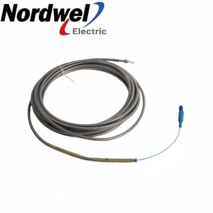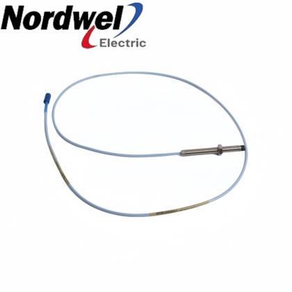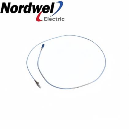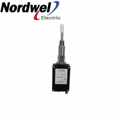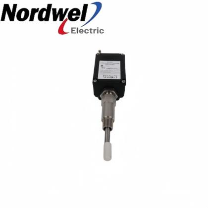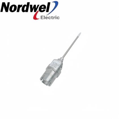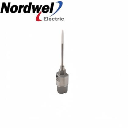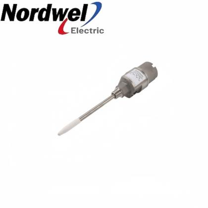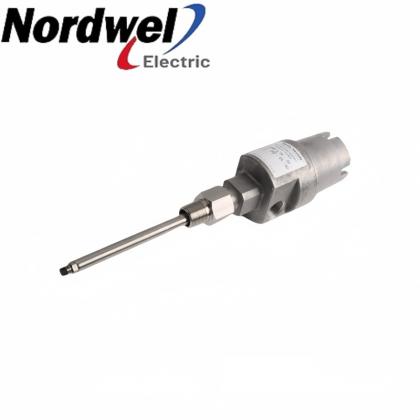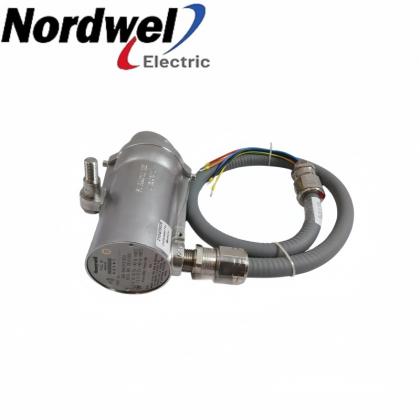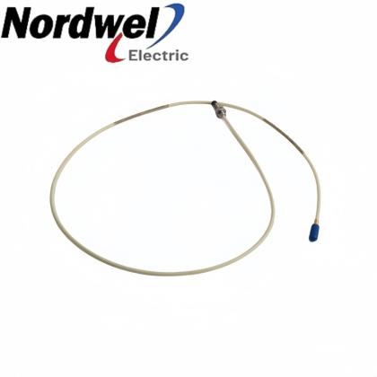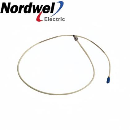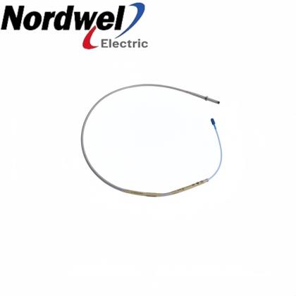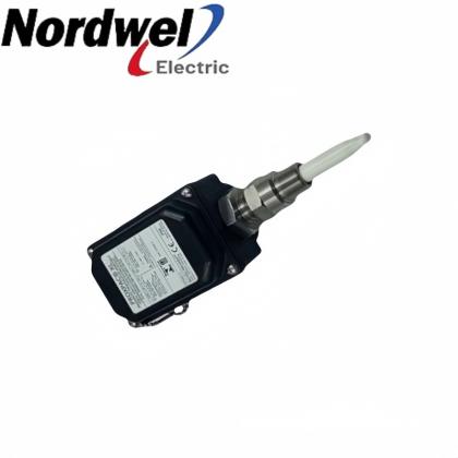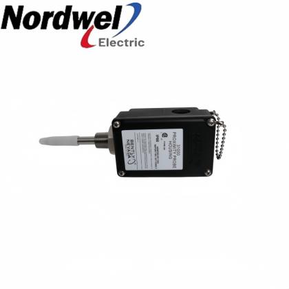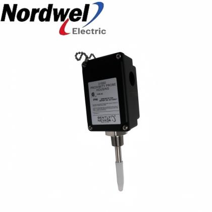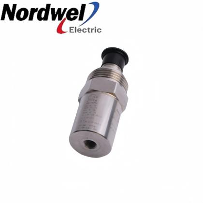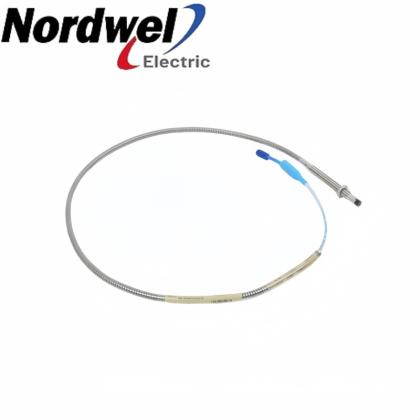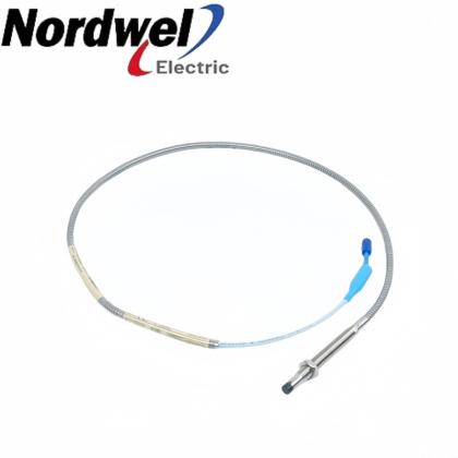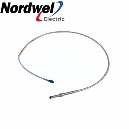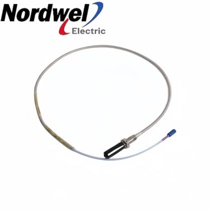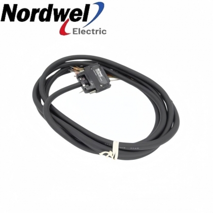
Bently Nevada 330851-01-000-030-10-00-05Inside the 12.7 mm Window
A model-specific reading of what this 3300 XL 25 mm proximity probe is designed to measure—and what its long ordering code does not decide on its own.
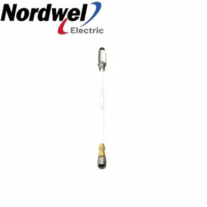
A current review of Bently Nevada ordering information places 330851-01-000-030-10-00-05 inside a much larger engineering story than its label first suggests. It is a specific one-metre, non-armored, multi-approval version of the 3300 XL 25 mm proximity probe. Its purpose, however, cannot be understood from the suffix alone. The decisive context is a complete transducer system built to observe differential expansion on mid-size to large steam turbine generators.
What happens when the rotor and the casing do not grow at the same rate?
A steam turbine is not thermally motionless. As operating conditions change, the rotor and the surrounding stationary structure respond to heat on different timelines. Differential expansion is the relative change between those two structures. The measurement therefore concerns more than the movement of one metal surface: it concerns the relationship between two parts of the machine.
That distinction explains why Bently Nevada positions the 3300 XL 25 mm system for differential expansion rather than presenting the probe as a general-purpose description of “distance.” The measurement arrangement can use transducers observing a collar, complementary transducers on opposite sides of a collar, or a ramp-based arrangement. Manufacturer guidance says the available target, expected axial movement and target geometry influence the selection.
In a collar arrangement, the transducers observe an axial target surface some distance from the thrust bearing. Two probes can view the same side of the collar, providing two measurements of the same movement. Where the physical target allows it, the manufacturer identifies this same-side arrangement as the preferred configuration because the two channels provide redundant measurements.
A complementary-input arrangement works differently. Two transducers observe opposite sides of a collar, allowing their signals to be combined and effectively extending the differential-expansion distance that can be measured. A ramp arrangement can cover a still longer total distance, but the manufacturer notes that radial motion can introduce additional error. The second transducer is therefore used to compensate for that radial component.
This is why a probe part number cannot define the entire application. The available collar height, expected axial movement and the presence of a collar or ramp determine how the sensors should be positioned. The probe code establishes the supplied hardware form; the turbine geometry establishes how that hardware may be used.
Rotor response
The rotating assembly changes length as its temperature and operating state change. The relevant movement is axial and must be interpreted relative to the stationary structure.
Casing response
The machine stator or casing also expands, but not necessarily by the same amount or at the same rate. The difference between the two is the engineering quantity of interest.
For international buyers, this distinction is commercially important. An RFQ that identifies only “a 25 mm differential-expansion probe” may still leave the mounting method, target form and required measurement span unresolved. A responsible quotation should preserve those open questions instead of turning them into unsupported assumptions.
The important number is not only “25 mm.”
The 25 mm name identifies the probe family. It is not the published linear measurement range. For the complete 3300 XL 25 mm transducer system, the manufacturer specifies a 12.7 mm (500 mil) linear range and a nominal average scale factor of 0.787 V/mm (20 mV/mil). The documented linear region begins at approximately 0.63 mm from the target and extends to approximately 13.33 mm under the stated test conditions.
The scale factor describes the nominal relationship between physical displacement and electrical output for the complete transducer chain. It should not be applied as though the probe were a stand-alone measuring device. The published performance specifications are based on a matching 25 mm probe, extension cable and Proximitor Sensor operating together under defined electrical, temperature and target conditions.
The manufacturer’s reference conditions also matter. Its core specifications use a supplied AISI 4140 steel target of at least 61 mm diameter and a nominal 7.0 mm probe gap. Factory Proximitor Sensors are calibrated to AISI 4140 steel by default, while calibration for other target materials is available by request. A different shaft or target material should therefore be treated as an engineering input, not as an invisible substitution.
These figures describe system performance under the conditions stated in the manufacturer’s datasheet. They do not determine the correct bracket, target geometry, installed gap or monitor configuration for a particular turbine. Those decisions remain part of the application record.
The wide range is valuable because differential expansion can involve considerably more axial travel than ordinary radial-vibration measurements. Yet a wide published range does not remove the need to establish the expected cold and hot positions. The installed gap has to leave usable travel in the required direction while remaining inside the system’s documented linear region.
Temperature also changes the performance boundary. The manufacturer publishes additional deviation limits when the probe, cable and Proximitor Sensor move beyond the standard reference temperatures. A project should therefore use the applicable system specification rather than quoting only the room-temperature scale factor.
Manufacturer reference: Bently Nevada 3300 XL 25 mm Proximity Transducer System Datasheet 163236 Rev. M.
Every code block answers a different identification question.
Select a segment below to see exactly what the manufacturer’s ordering structure establishes. This is a decoding exercise, not a compatibility approval.
330851 · Product identity
3300 XL 25 mm Proximity Probe. This identifies the probe family. It does not by itself identify the required extension cable, Proximitor Sensor, bracket arrangement or receiving monitor.
01 · Probe case type
1¼-12 thread. The official family also includes metric threaded cases and smooth rear- or side-exit cases, so “25 mm probe” is not enough to confirm the mechanical form.
000 · Unthreaded length
0.0 inch. For English threaded cases, this three-digit field is ordered in 0.1-inch increments; 000 represents the standard zero unthreaded-length selection for this configuration.
030 · Overall case length
3.0 inches. This is one of the standard English case lengths listed by the manufacturer. It is a physical case dimension, not the probe lead length.
10 · Total probe length
1.0 metre (3.3 feet). The system-length relationship still has to be respected: the probe length plus the extension-cable length must equal the Proximitor Sensor total length.
00 · Armor option
No armor. This code should not be described as an armored probe. The standard FluidLoc probe cable and the optional stainless-steel armor are separate construction facts.
05 · Agency approval option
Multiple approvals. The required country- and product-specific documentation must still be checked against the applicable approvals reference and the destination requirement.
Important: the manufacturer lists this full code among commonly stocked multi-approval probes. That is a product-document statement, not confirmation of today’s inventory, quantity, condition, price or delivery date.
Reading the code from left to right also prevents several common purchasing errors. The 030 field is an English-case dimension of 3.0 inches; it is not a 30 mm metric length. The 10 field describes the one-metre total probe length; it is not a ten-metre cable. The 00 field confirms that the optional stainless-steel armor is absent, even though the probe still uses the standard FluidLoc cable construction described for this family.
The multiple-approval suffix should be handled with the same care. It identifies an ordering option, but it does not tell the receiving team which certificate, installation drawing or hazardous-area condition applies at a specific destination. Bently Nevada directs users to its approvals quick-reference material for the detailed country- and product-specific listing.
Likewise, inclusion in a commonly stocked list should not be translated into a promise that a particular supplier has an item ready to ship. The datasheet describes a manufacturer ordering practice. A current commercial offer still needs a dated availability statement, quantity, condition, traceability evidence and agreed inspection scope.
A probe is one component—not the complete measurement system.
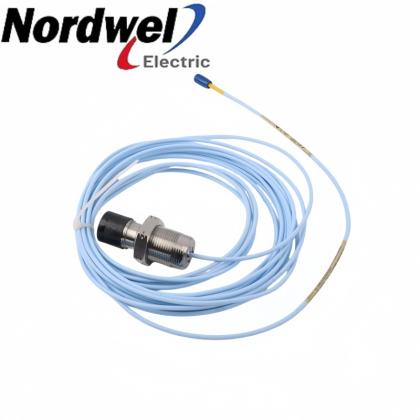
Bently Nevada defines the 3300 XL 25 mm transducer system as three principal elements: a proximity probe, an extension cable and a Proximitor Sensor. The exact probe in this review has a one-metre total length. Official 25 mm extension-cable options include four and eight metres, while the associated Proximitor Sensor configurations use five- or nine-metre total system lengths.
The extension cable is not an arbitrary length added for installation convenience. Its electrical characteristics are part of the calibrated system. With a one-metre probe, a four-metre extension cable forms the five-metre system, while an eight-metre extension cable forms the nine-metre system. The Proximitor Sensor ordering code must identify the corresponding total length.
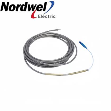
For this 25 mm family, Bently Nevada specifies high-temperature FluidLoc cable construction for the extension cable, with a separate option for stainless-steel armor. The probe itself uses PFA-insulated 75-ohm triaxial FluidLoc cable. The FluidLoc construction and the probe’s front and rear seals are intended to resist moisture entering the probe tip; they should not be confused with the separate armor choice encoded in the part number.
25 mm probe
Mechanical case, probe lead, armor choice and approval option are encoded in the complete part number.
Extension cable
Length, high-temperature FluidLoc construction, optional armor and approval selection require their own full code.
Proximitor Sensor
Total system length, mounting form and approval option must align with the selected probe-and-cable combination.
That relationship is why a photograph of one probe label cannot close every engineering question. A reliable inquiry should also capture the extension-cable and Proximitor Sensor labels, the installed arrangement and the project-controlled documentation.
The connectors carry their own engineering details. High-temperature ClickLoc connectors are standard on the probe and extension cable, and the probe-lead connector has a removable collar to support routing through restricted clearances. Connector protectors and an installation tool are supplied to help keep the mating surfaces free of contamination. These features support handling and installation, but they do not change the requirement to match the three system components correctly.
The temperature ratings also belong to specific components. The probe and extension cable are documented for operation and storage from −35°C to +200°C, with the probe capable of withstanding +250°C for less than 24 hours. The Proximitor Sensor has a different published operating range. A statement that the “system is rated to 200°C” would therefore be too broad unless it clearly identifies which component is exposed to that temperature.
Separate what the code proves from what the site must still prove.
Established by the official code
- 3300 XL 25 mm proximity-probe family
- 1¼-12 threaded probe case
- 0.0-inch unthreaded length
- 3.0-inch overall case length
- 1.0-metre total probe length
- No optional stainless-steel armor
- Multiple-approval ordering option
Still requires project evidence
- Correct mounting method for the actual target
- Required initial gap and expected axial travel
- Matching extension cable and Proximitor code
- Compatibility with the installed channel and records
- Required approval documents for the destination
- Current stock, condition, price and delivery
- Final acceptance of any replacement or upgrade
A model-specific review is most useful when it shows both sides of the evidence boundary. The part number is strong evidence for the supplied probe’s construction, but it is weak evidence for the surrounding installation unless the matching records are also available. This is especially important for removed spares, repaired equipment and legacy machines whose labels may have been separated from the original drawings.
Condition and compatibility should also remain separate decisions. A factory-new probe can still be the wrong thread, case length or system length. An accurately identified used probe can still require a condition assessment. Combining those questions into a single “same model” statement makes the quotation shorter, but it does not make the decision safer.
The same discipline applies to legacy-system discussions. Manufacturer documentation states that 3300 XL 25 mm configurations can physically replace several earlier 7200 and 25 mm DE Integral arrangements, and that the Proximitor output supports upgrades without monitor-configuration changes in the described cases. It also states that every transducer-system component must be replaced with the corresponding 3300 XL 25 mm component during such an upgrade. A mixed-component assumption is therefore not supported by that guidance.
This compatibility statement has a precise scope. It does not mean that any 25 mm probe can be inserted into any earlier installation without reviewing case style, bracket, target geometry, cable length and channel documentation. It means the manufacturer has designed 3300 XL configurations to support the stated upgrade path when the complete system is selected and replaced according to its guidance.
Four questions that should be answered before an exact-match claim.
An exact-match claim should be reproducible by someone who did not prepare the original RFQ. The evidence should allow engineering, purchasing, receiving and the supplier to reach the same conclusion without relying on an undocumented phone call or a cropped photograph.
For a routine spare, the review may be brief because the labels, drawing and installed record already agree. For an obsolete, repaired or previously substituted system, the same four questions become a structured investigation. Leaving one answer open is better than filling the gap with an assumption that will surface after shipment.
1. Do all three system labels agree?
Record the complete probe, extension-cable and Proximitor Sensor codes. Confirm that the one-metre probe and selected extension cable add up to the total system length encoded by the Proximitor Sensor.
2. Does the mechanical geometry agree?
The reviewed code identifies a 1¼-12 threaded, 3.0-inch overall case. The installed thread, available insertion geometry, bracket and target arrangement must support that form.
3. Does “no armor” match the installation?
The 00 armor field means no optional stainless-steel armor. Do not convert a visual preference or a nearby armored cable into a claim that this exact code includes armor.
4. Are approvals and commercial evidence complete?
The 05 suffix means the multiple-approval option, but the applicable country-specific records still need review. Separately confirm supplier identity, item condition, label photographs, inspection scope, packing, quantity and delivery terms.
Installation verification remains a physical task. Bently Nevada states that correct operation should be checked by moving the transducer system to simulate shaft-collar motion. Its optional sliding bracket and dial-indicator verification kit are intended to support movement through the linear range while maintaining alignment and perpendicularity to the rotor. This confirms why a datasheet value alone cannot substitute for the installed verification procedure.
Short answers for model-specific inquiries.
The questions below address the points most likely to be compressed or lost when a long model code moves between engineering, purchasing and an international supplier. They are deliberately limited to conclusions supported by the manufacturer’s published ordering information.
Is 330851-01-000-030-10-00-05 armored?
No. The EE field is 00, which the official ordering table defines as “No Armor.”
Does “25 mm” mean a 25 mm measuring range?
No. It identifies the probe family. The complete transducer system has a published 12.7 mm linear range under the manufacturer’s stated conditions.
Can the probe operate by itself?
It belongs to a system that includes the matching extension cable and 3300 XL 25 mm Proximitor Sensor. The complete chain controls system performance.
Is the exact code officially recognized?
Yes. The manufacturer’s ordering information lists this full number among commonly stocked multi-approval probes. This does not guarantee current availability.
What temperature is published for the probe?
The datasheet publishes −35°C to +200°C for operating and storage, with a short-term maximum of +250°C for less than 24 hours. Application limits must be checked as a complete system.
What should be sent with an RFQ?
Send all available label photographs, quantity, destination, required condition, installation records, extension-cable and Proximitor codes, and any project-controlled drawing or specification.
Start with the complete evidence set.
For Bently Nevada 330851-01-000-030-10-00-05, a defensible inquiry connects the exact probe code to mechanical geometry, the extension cable, Proximitor Sensor, installation record and commercial inspection scope.