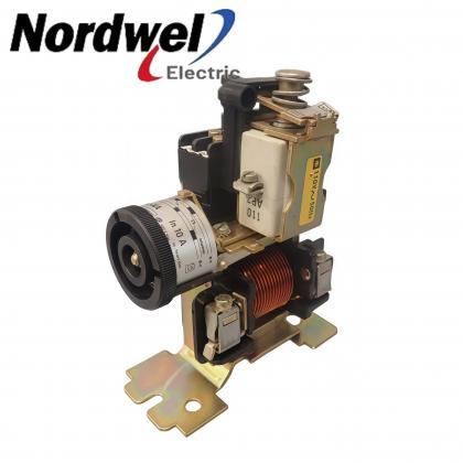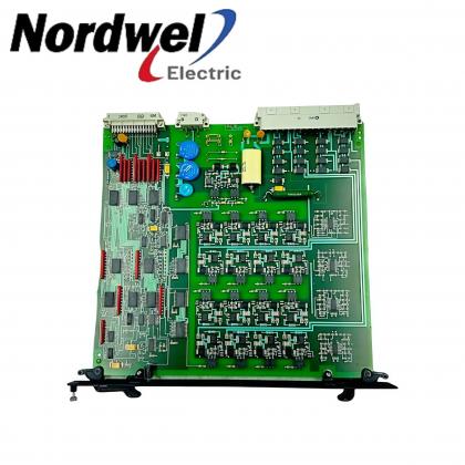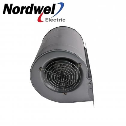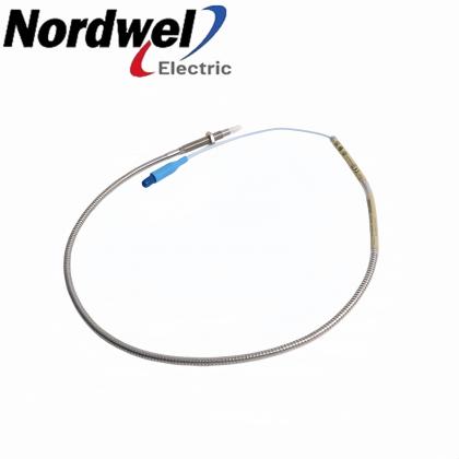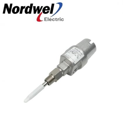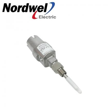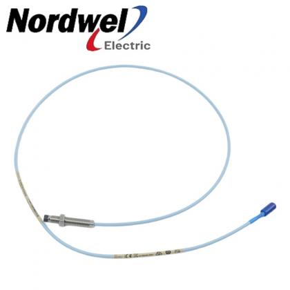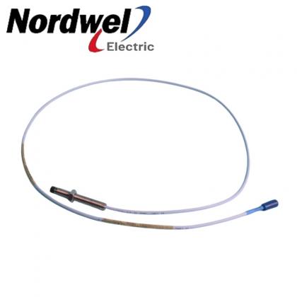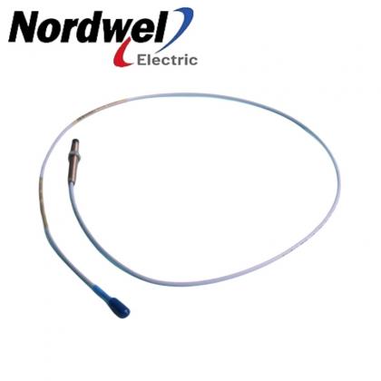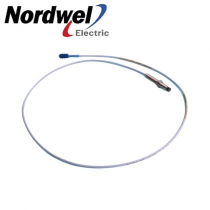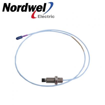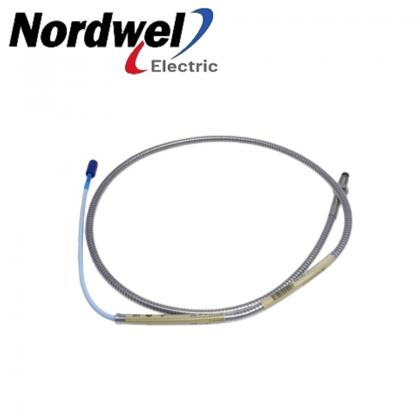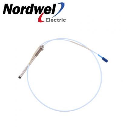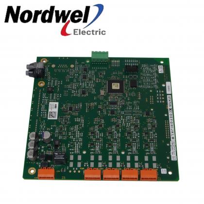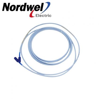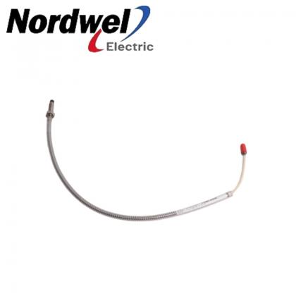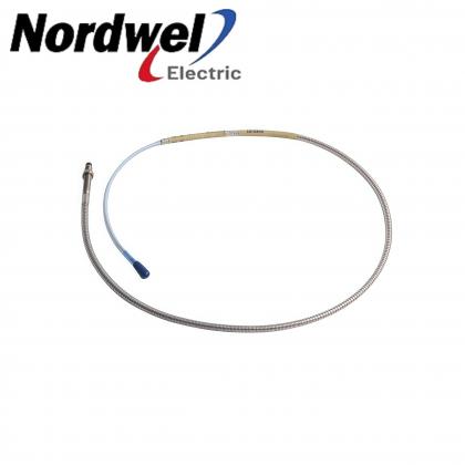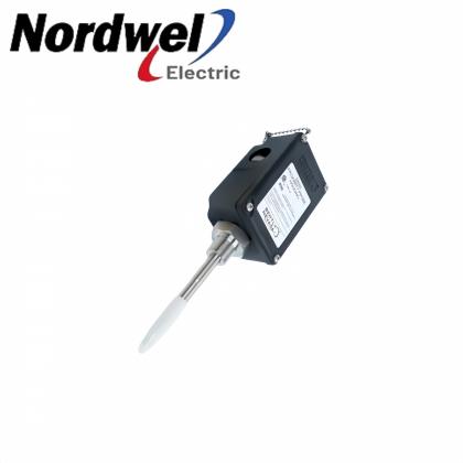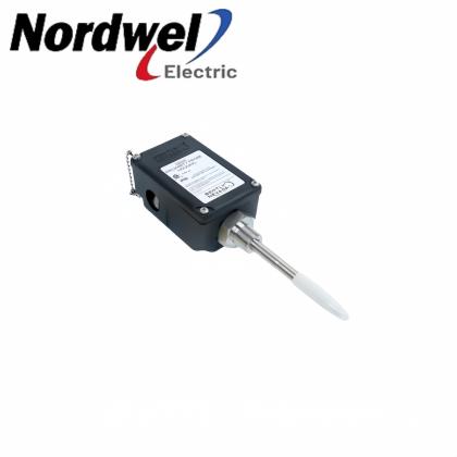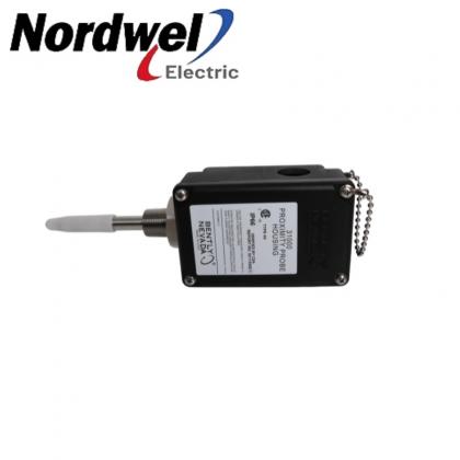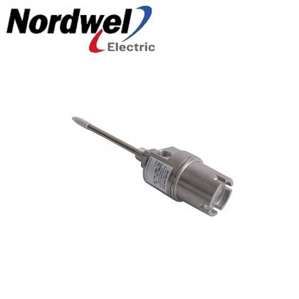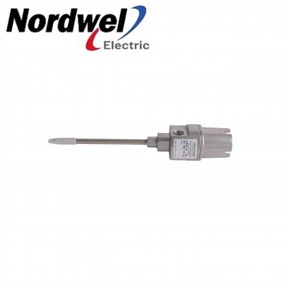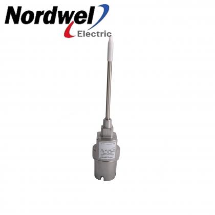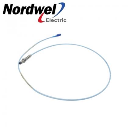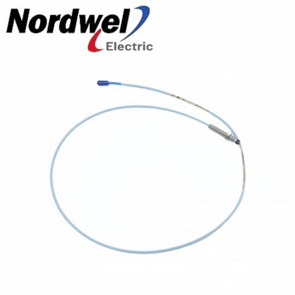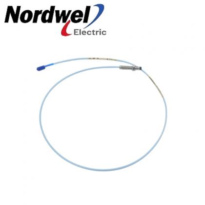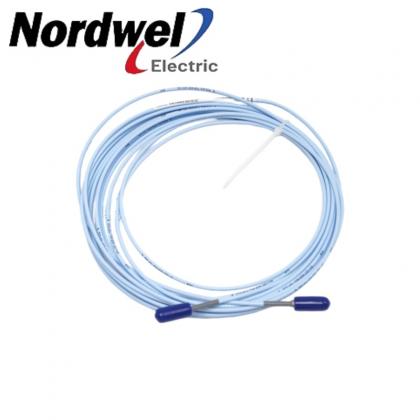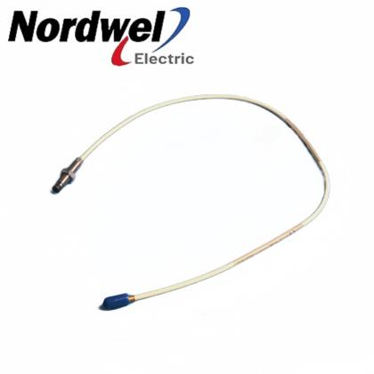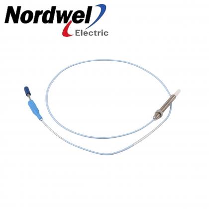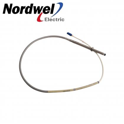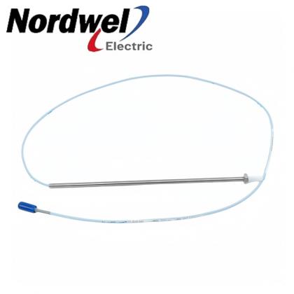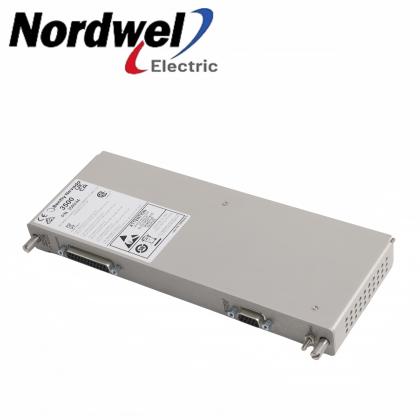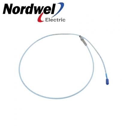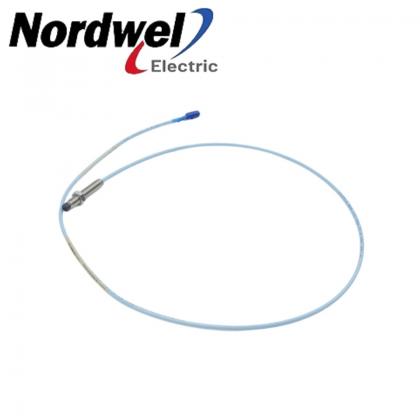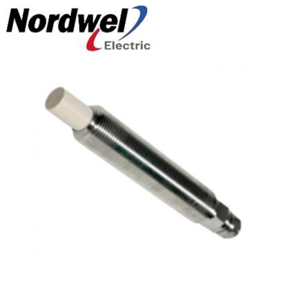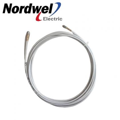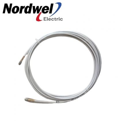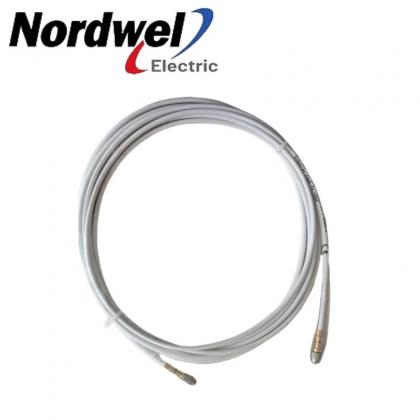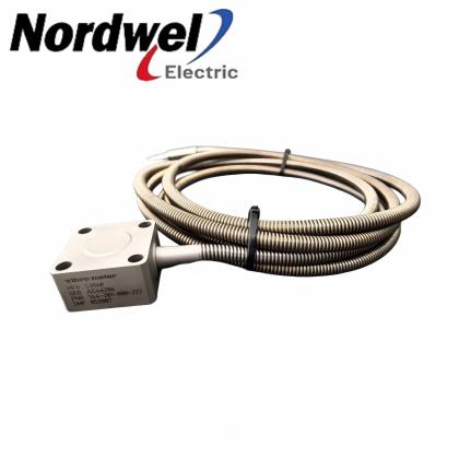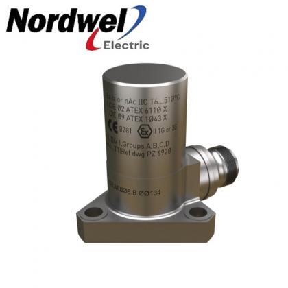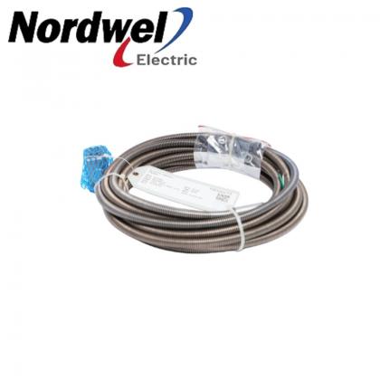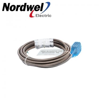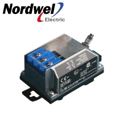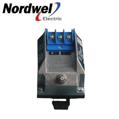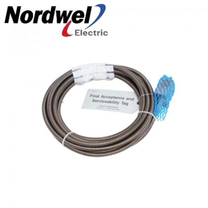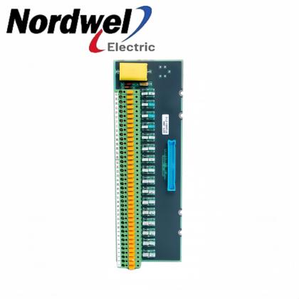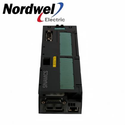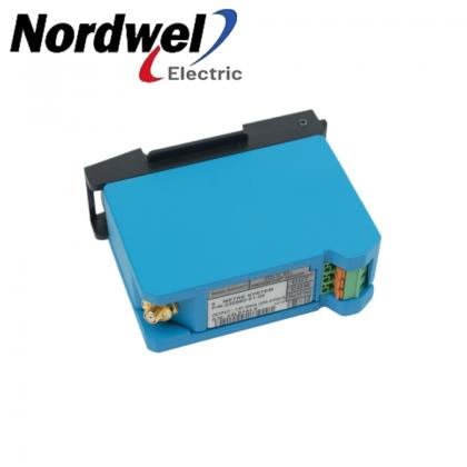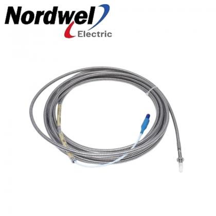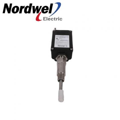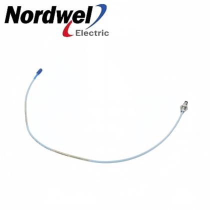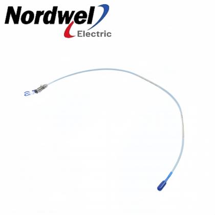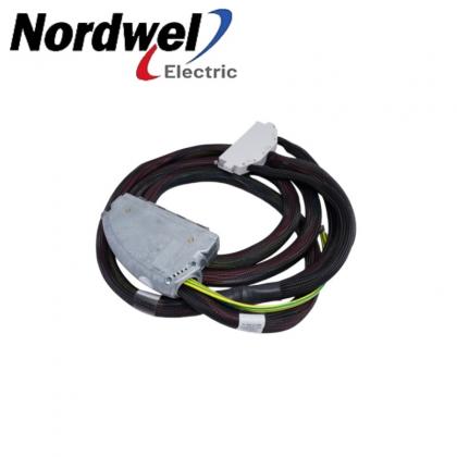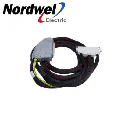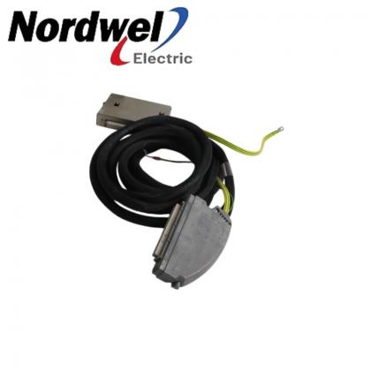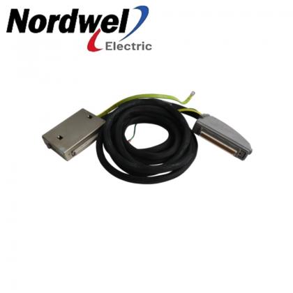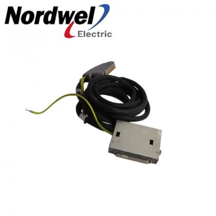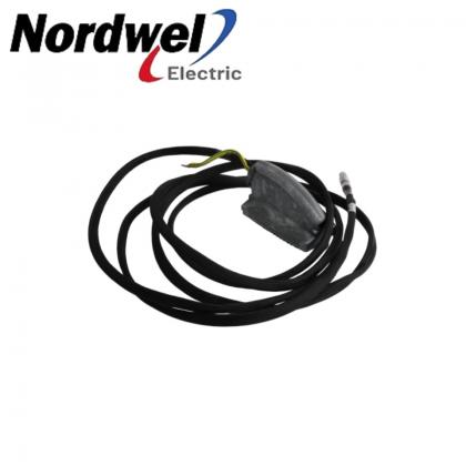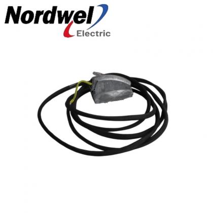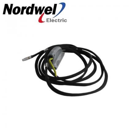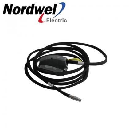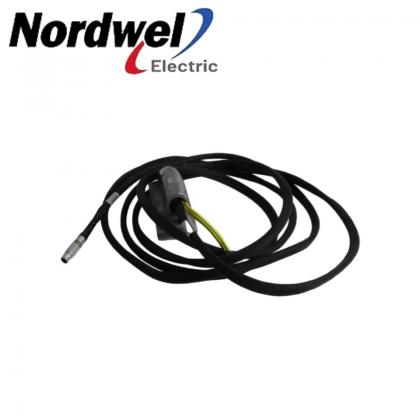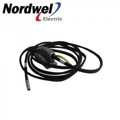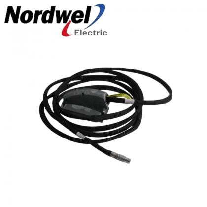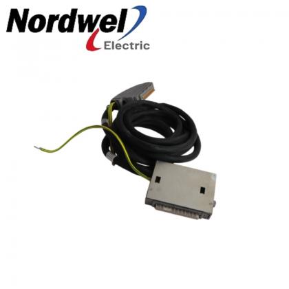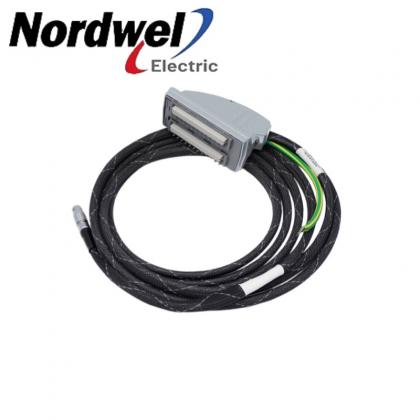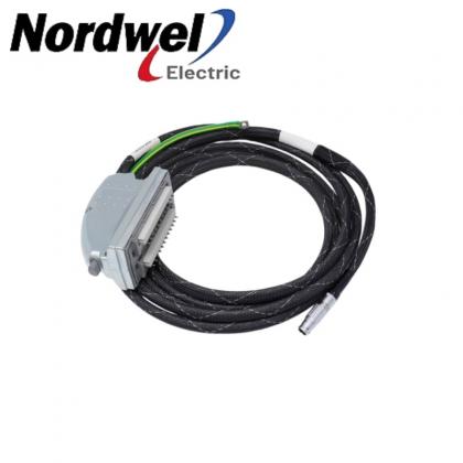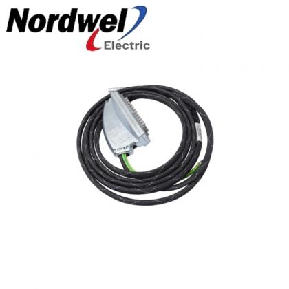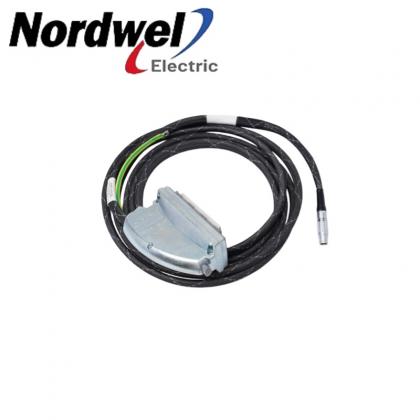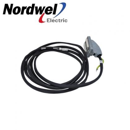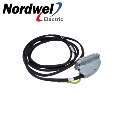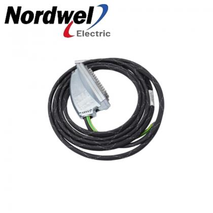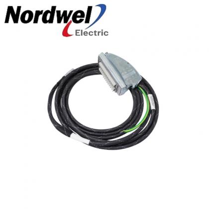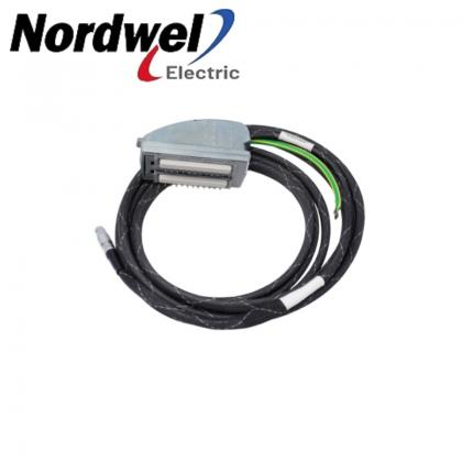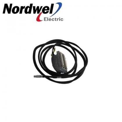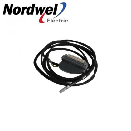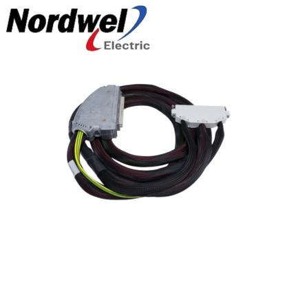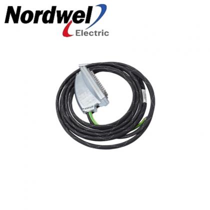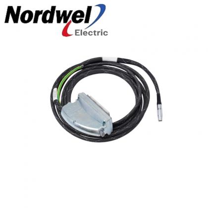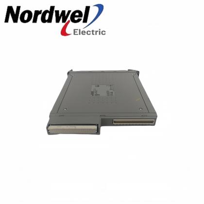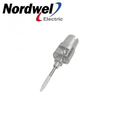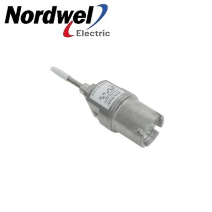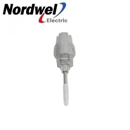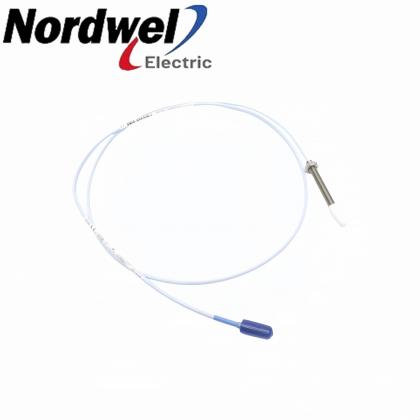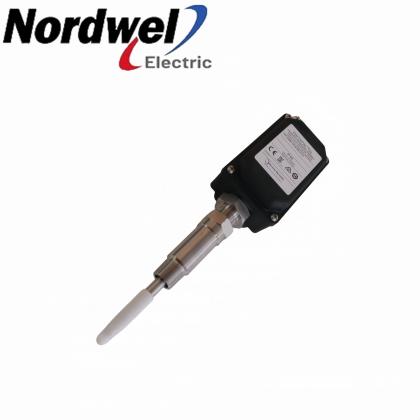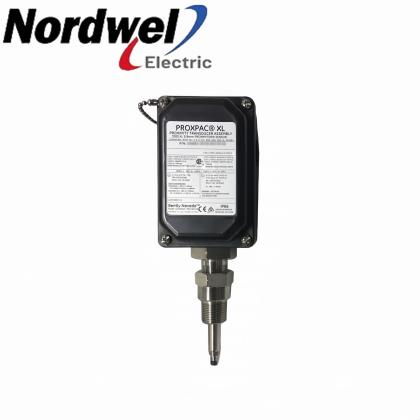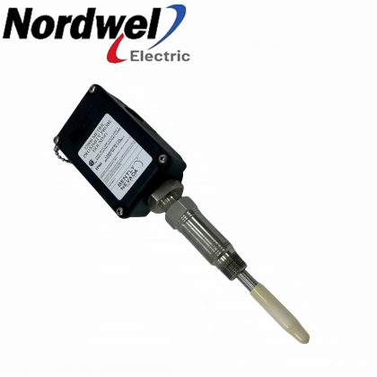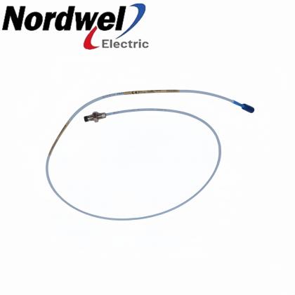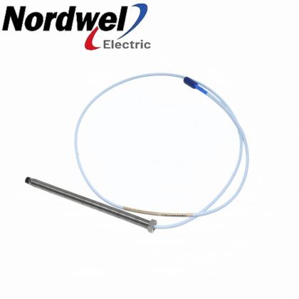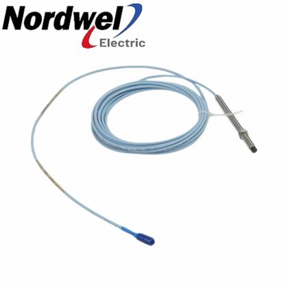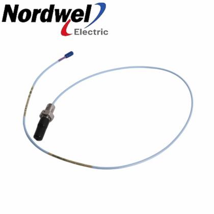
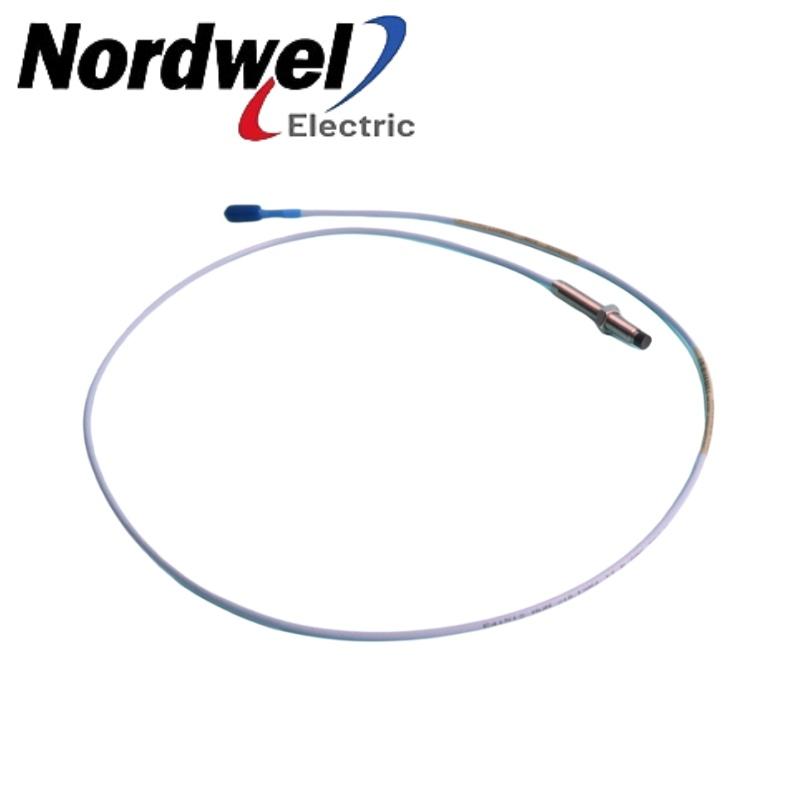
330101-65-96-10-02-003/8-24 UNF · Without Armor
Related exact 3300 XL 8 mm configuration; verify the complete suffix before selection.
View productReliable shaft data starts with the exact probe configuration.
A manufacturer-sourced technical and procurement briefing for teams managing turbines, compressors, pumps, generators and other fluid-film bearing machinery.
September 4, 2026 — As industrial operators expand online condition monitoring, remote diagnostics and data-driven maintenance programs, greater attention is being directed toward the quality of the measurements entering those systems.
Analytics can identify trends only when the underlying sensor chain is correctly selected, installed and maintained. For rotating machinery, an unstable shaft-vibration or position signal can complicate fault diagnosis, weaken historical comparisons and lead maintenance teams toward the wrong conclusion.
This places renewed focus on the Bently Nevada 330102-04-16-10-02-00, an armored 3300 XL 8 mm proximity probe configured for non-contacting shaft vibration and position measurement as part of a complete Bently Nevada proximity transducer system.
The important procurement point is that this long ordering code is not incidental. Each field identifies a mechanical, cable or approval characteristic that should be matched against the installed application.
Source and method: Technical values and ordering-code interpretations in this briefing were checked against current Baker Hughes/Bently Nevada manufacturer documentation. Procurement and diagnostic guidance is editorial analysis and does not replace the manufacturer's instructions or the plant's approved procedures.
The 330102-04-16-10-02-00 is a standard-temperature, standard-mount 3300 XL 8 mm proximity probe with:
System boundary: It is a probe component—not a complete independent monitoring system. The connected Proximitor Sensor, system length, target material, mounting arrangement and monitor input must also be confirmed.
The 330102-04-16-10-02-00 belongs to the Bently Nevada 3300 XL 8 mm Proximity Transducer System.
According to Baker Hughes, a complete 3300 XL 8 mm system normally consists of:
The system generates an output voltage proportional to the distance between the probe tip and the observed conductive surface. It can therefore measure static values, such as shaft position, and dynamic values, such as shaft vibration.
The manufacturer identifies its primary uses as vibration and position measurement on fluid-film bearing machines, together with Keyphasor reference and speed measurement applications. Baker Hughes advises consulting its dedicated application note when considering the system for tachometer or overspeed measurements.
The 330102-04-16-10-02-00 should not be described as a general-purpose object-detection switch, magnetic sensor or standalone vibration transmitter. It is one component in an eddy-current proximity measurement chain.
For this probe, the full part number provides information that the abbreviated description “3300 XL 8 mm probe” cannot supply.
| Code | Official configuration | Why it matters |
|---|---|---|
| 330102 | 3300 XL 8 mm probe, 3/8-24 UNF thread, with armor | Defines the probe family, imperial thread and armored construction |
| 04 | 0.4-inch unthreaded length | Must suit the probe bracket, machine geometry and required insertion depth |
| 16 | 1.6-inch overall case length | Affects mounting access and usable threaded engagement |
| 10 | 1.0-meter total length | Determines the electrical system configuration and cable routing |
| 02 | Miniature coaxial ClickLoc connector, standard cable, without connector protector | Must match the receiving component and site protection requirements |
| 00 | Agency approval not required | Does not specify the CSA, ATEX and IECEx approval option |
The final 00 means that an agency approval option was not required in the ordered configuration. Baker Hughes lists 05 as the ordering option for CSA, ATEX and IECEx approvals.
This distinction is important for refineries, chemical plants, gas-processing facilities and other sites with hazardous-area requirements. Buyers should not assume that every 3300 XL 8 mm probe carries the same approval simply because the mechanical design appears identical.
The complete nameplate, area classification, applicable certificate and installed system drawing should be reviewed before approving a replacement.
The probe observes the gap between its tip and a conductive shaft surface. When the shaft moves, the transducer system converts the changing gap into an electrical output that can be used for vibration and position monitoring.
This data can support the evaluation of radial shaft vibration, shaft centerline movement, axial position, speed and phase-reference behavior. The probe does not independently diagnose imbalance, misalignment, oil whirl, rubs or bearing problems. Those conclusions depend on the complete measurement chain, machine configuration, operating data and qualified analysis.
Predictive maintenance programs increasingly rely on continuous machinery data rather than isolated inspection results. However, the credibility of a trend depends on consistency across the full signal path:
A damaged probe tip, incorrect gap, unsuitable cable routing, mismatched system length or loose connection may produce a signal that looks like a machinery change. Sensor-chain verification should therefore come before major maintenance decisions are based on the data.
The following values are taken from the Baker Hughes 3300 XL 8 mm Proximity Transducer System datasheet. System performance values apply under the test conditions and component combinations defined by the manufacturer.
| Item | Official characteristic | Practical significance |
|---|---|---|
| Measurement principle | Non-contacting eddy-current proximity measurement | Supports static position and dynamic vibration measurement |
| Standard system linear range | 2 mm (80 mils), approximately 0.25 to 2.3 mm from the target | “8 mm” is not the measuring range |
| Scale factor | 7.87 V/mm (200 mV/mil) ±5% for standard 1 m or 5 m systems at 0°C to +45°C, including interchangeability error | The monitor and analysis configuration must use the correct scale |
| Frequency response | 0 to 10 kHz, +0/-3 dB with up to 305 m (1,000 ft) of field wiring under the stated conditions | Supports dynamic machinery measurements within the specified system response |
| Standard probe temperature range | −52°C to +177°C | Temperature suitability must be checked at the actual probe location; the manufacturer notes that exposure below −34°C may cause premature pressure-seal failure |
| Standard probe cable | 75-ohm triaxial cable with FEP insulation | The cable is part of the electrical characteristics of the system |
| Armor construction | Flexible AISI 302 or 304 stainless steel with FEP outer jacket | Provides added mechanical protection for the probe lead |
| Minimum cable bend radius | 25.4 mm (1.0 inch) | Tight routing can place stress on the cable and connector |
| Probe-to-lead tensile rating | 330 N (75 lbf), maximum rated | A published rating—not permission to pull or suspend the probe by its cable |
| Maximum thread engagement | 0.563 inch for 3/8-24 thread | Excessive engagement may cause binding during installation |
Baker Hughes states that the standard 3300 XL 8 mm five-meter system complies with API 670 requirements for mechanical configuration, linear range, accuracy and temperature stability.
That statement should not be shortened into “every 330102 probe is API 670 compliant” without qualification. API performance relates to the defined transducer system and configuration, not simply the presence of an 8 mm probe.
The 330102 family uses armored probe cable construction. This is particularly relevant where the probe lead may be exposed to maintenance activity, abrasion or demanding routing conditions.
However, armor does not eliminate installation limits. Maintenance teams should:
Because option 02 specifies a ClickLoc connector without a factory-installed connector protector, the environmental protection method at the connection deserves particular attention.
The 10 field specifies a total probe length of one meter. Baker Hughes states that one-meter systems do not use an extension cable.
This makes the configuration physically simpler, but it does not make the probe a complete system by itself. A compatible Proximitor Sensor and monitoring input are still required.
Before replacement, confirm:
Adding an extension cable simply because the connector fits can change the electrical length and compromise system performance.
Baker Hughes documents component interchangeability as an advantage of the 3300 XL 8 mm system. Probes, extension cables and Proximitor Sensors can be interchanged within the applicable system family without individually matching or bench-calibrating each component.
The manufacturer also documents backward compatibility with certain non-XL 3300-series 5 mm and 8 mm components. However, mixing XL and non-XL components limits system performance to the specifications of the non-XL system.
Interchangeability therefore does not mean that any visually similar probe, cable or Proximitor can be combined without review. Product family, total system length, connector type, target material, approvals, monitor scaling and mechanical dimensions must still agree.
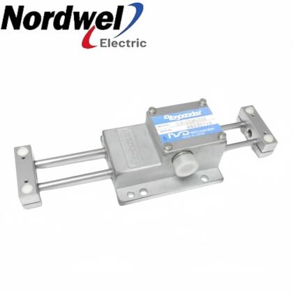
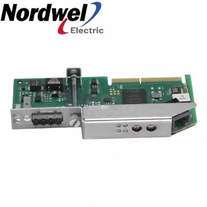
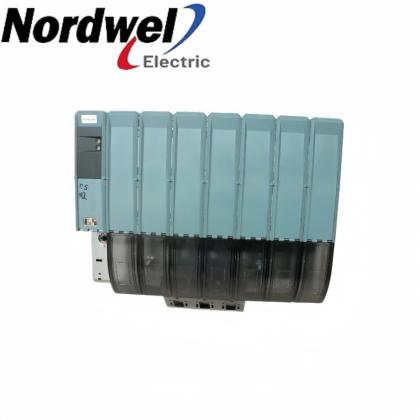
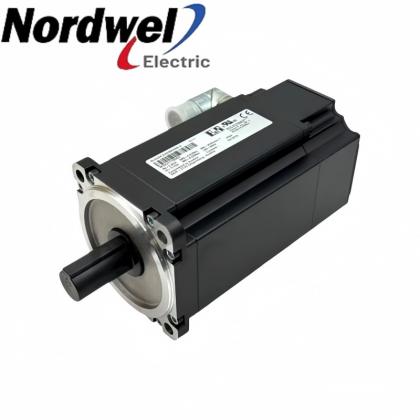
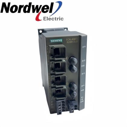
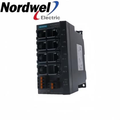
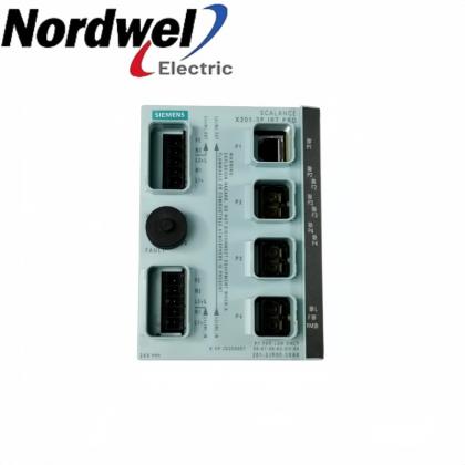
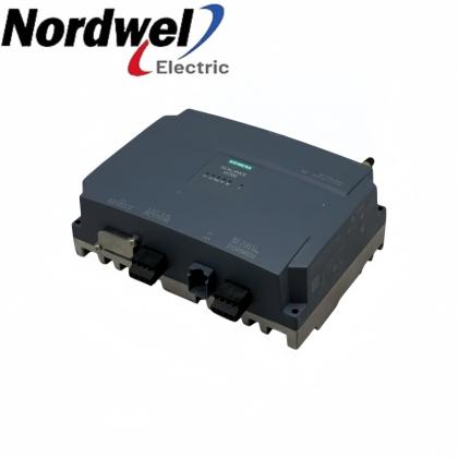
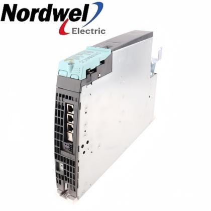
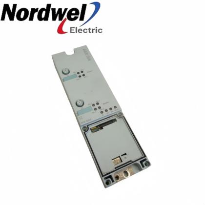
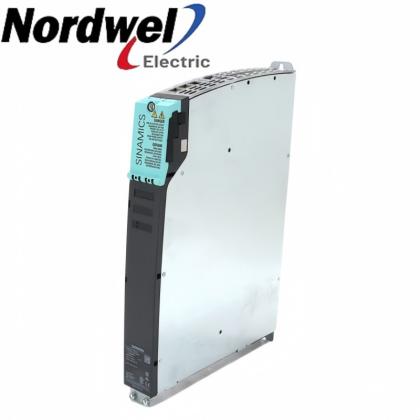
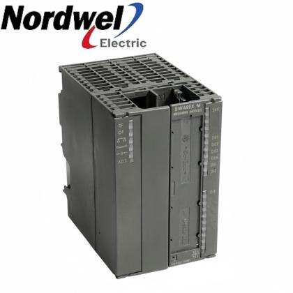
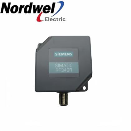
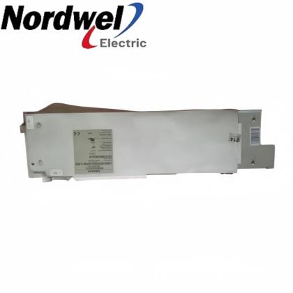
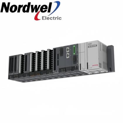
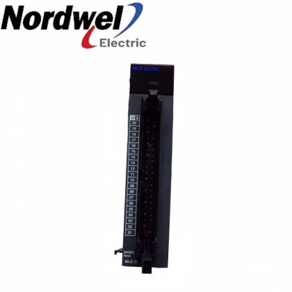
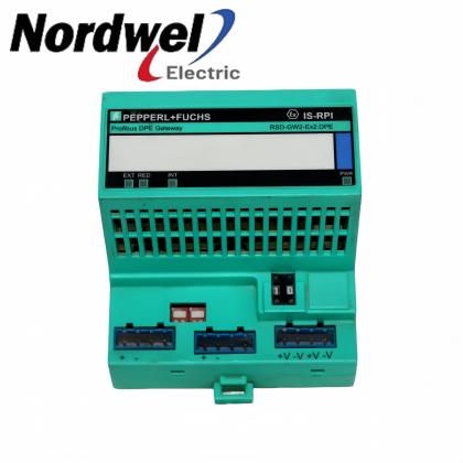
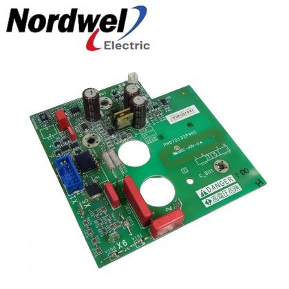
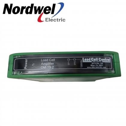
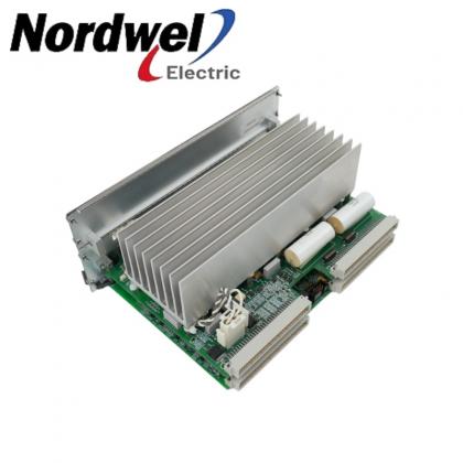
Open any group to compare two linked Nordwel product configurations with product photography.
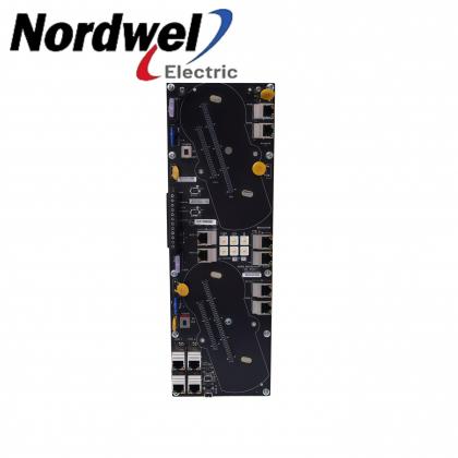
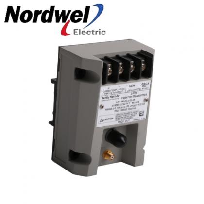
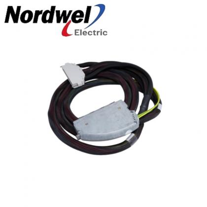
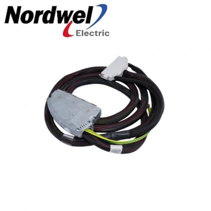
Related exact 3300 XL 8 mm configuration; verify the complete suffix before selection.
View product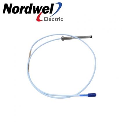
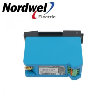
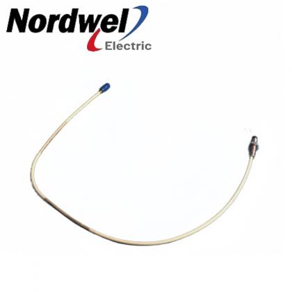
Related exact 3300 XL 8 mm configuration; verify the complete suffix before selection.
View product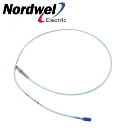
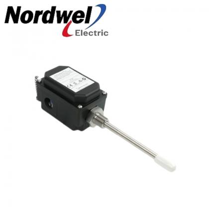
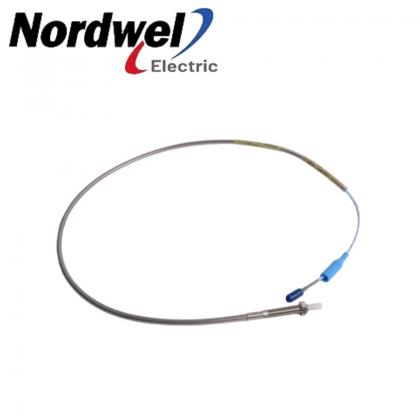
Related exact 3300 XL 8 mm configuration; verify the complete suffix before selection.
View product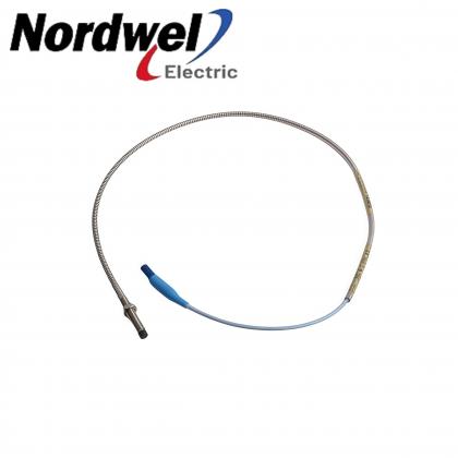
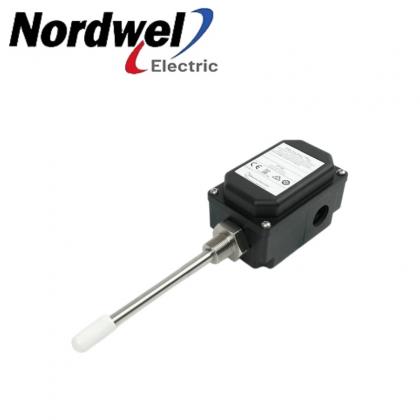
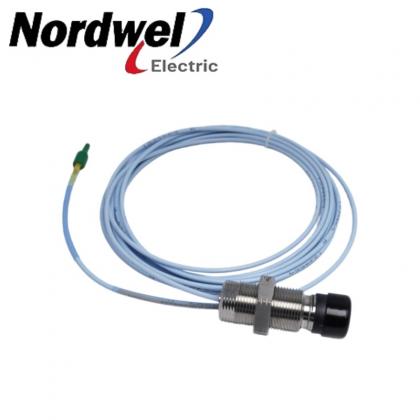
Related exact 3300 XL 8 mm configuration; verify the complete suffix before selection.
View product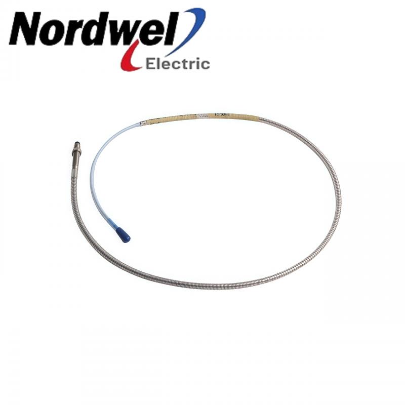
Related exact 3300 XL 8 mm configuration; verify the complete suffix before selection.
View product
Related exact 3300 XL 8 mm configuration; verify the complete suffix before selection.
View product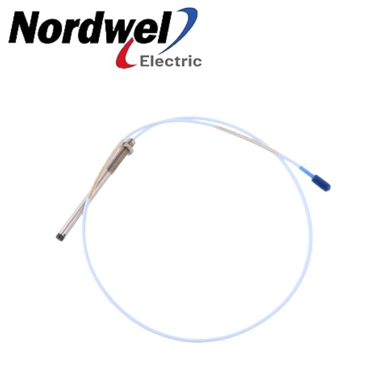
Related exact 3300 XL 8 mm configuration; verify the complete suffix before selection.
View product
Related exact 3300 XL 8 mm configuration; verify the complete suffix before selection.
View product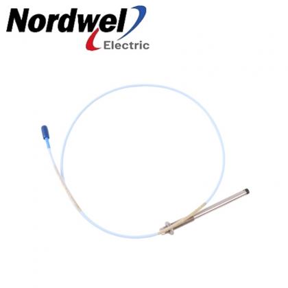
Related exact 3300 XL 8 mm configuration; verify the complete suffix before selection.
View product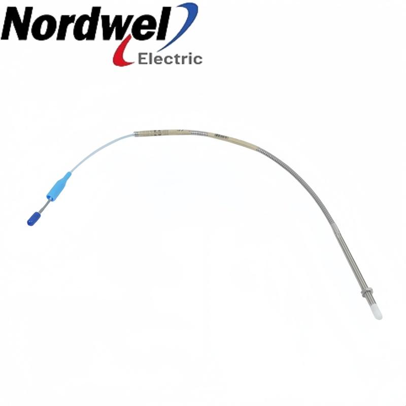
Related exact 3300 XL 8 mm configuration; verify the complete suffix before selection.
View product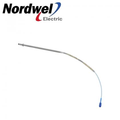
Related exact 3300 XL 8 mm configuration; verify the complete suffix before selection.
View product
Related exact 3300 XL 8 mm configuration; verify the complete suffix before selection.
View productSelection boundary: These links show related exact configurations, not automatic direct replacements. Confirm the complete part number, dimensions, system length, connector, approval option, target material and installed Proximitor Sensor before purchase.
Conditions that justify inspection of the proximity measurement chain may include:
These observations do not automatically prove that the probe is defective. The cause may be an incorrect gap, shaft-surface condition, mounting movement, connector contamination, cable damage, an incorrect system-length combination, Proximitor or field-wiring problems, monitor configuration or genuine machinery behavior.
A controlled diagnostic process should separate a sensor-chain fault from a mechanical condition before equipment is replaced or alarm settings are changed.
For an accurate quotation and replacement review, the RFQ should include:
After confirming technical suitability, procurement teams should compare product condition, traceable identification, availability, actual-item photographs, inspection scope, warranty, return conditions, packing method and dispatch time.
A lower quotation does not reduce total procurement cost if the supplied probe has the wrong case length, cable configuration, approval suffix or system-length relationship.
Availability, condition and warranty should always be confirmed in the formal quotation rather than assumed from a generic product listing.
Select a question to reveal the answer.
No. It is the proximity probe component. The complete measurement chain also requires the correct Proximitor Sensor and monitoring channel. A one-meter system does not normally use an extension cable.
No. The 8 mm designation refers to the probe family and physical probe-tip size. The manufacturer publishes a 2 mm nominal linear range for the standard transducer system under specified conditions.
The 04 field specifies a 0.4-inch unthreaded length. The 16 field specifies a 1.6-inch overall case length.
It specifies a one-meter total probe length. Baker Hughes states that one-meter systems do not use an extension cable.
No. Option 02 specifies a miniature coaxial ClickLoc connector with standard cable and no factory-installed connector protector.
The suffix means agency approval was not required for this ordering configuration. If CSA, ATEX or IECEx approval is required, verify the applicable approved option, certificate and site requirements before ordering.
Not on the family name alone. Compare the complete ordering number, thread, mechanical lengths, cable length, connector option, armor, approvals and system configuration.
Provide the complete part number, quantity, nameplate photographs, Proximitor Sensor model, extension-cable information, machine application, approval requirements and delivery destination.
The Bently Nevada 330102-04-16-10-02-00 remains relevant as plants place greater emphasis on predictive maintenance and credible rotating-equipment data. Its armored construction, defined mechanical configuration and one-meter probe length make it a specific engineered component—not a generic 8 mm proximity sensor.
Its value depends on correct application. The probe must be installed with the proper gap and mechanical clearances, connected to the correct system-length configuration and evaluated as part of the complete measurement chain.
For maintenance and procurement teams, the priority is clear: verify the full ordering code and installed transducer system before comparing price or approving shipment.
That process helps protect both machinery availability and the integrity of the vibration data used to support maintenance decisions.
Include the complete 330102-04-16-10-02-00 code, quantity, installed Proximitor Sensor, cable arrangement, application, approval requirement and delivery destination. These details support a faster and more controlled review.
For pricing, availability or configuration review, include the complete part number, quantity, installed system details and delivery destination.
sales2@mooreplc.comTechnical note: Specifications apply under the conditions and component combinations stated in the manufacturer’s documentation. Final installation, hazardous-area suitability, alarm configuration and commissioning should follow the applicable Bently Nevada instructions and the plant’s approved engineering procedures.


Disclaimer:
Nordwel sells new and surplus products and develops channels for purchasing such products. This website has not been approved or recognized by any of the listed manufacturers or trademarks.